
Jeep Wrangler Front Suspension Diagram
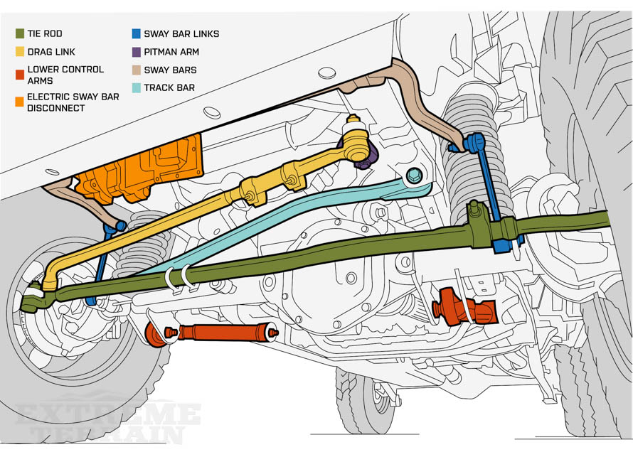
If you're elbow-deep in a Jeep Wrangler project, whether it's routine maintenance, a serious repair, or a full-blown modification, understanding the front suspension is absolutely crucial. This article dives deep into the Jeep Wrangler front suspension diagram, giving you the knowledge to confidently tackle almost any suspension-related task.
Why a Front Suspension Diagram Matters
A detailed diagram isn't just a pretty picture; it's your roadmap. It provides:
- Clarity for Repairs: Identify components, understand their relationships, and pinpoint the source of a problem.
- Guidance for Modifications: Plan lift kits, axle swaps, or suspension upgrades with a solid understanding of the existing setup.
- Educational Insight: Learn how the suspension works and how each part contributes to ride quality, handling, and off-road capability.
- Cost Savings: Diagnosing issues yourself can save you big bucks at the mechanic's shop.
Key Specs and Main Parts of the Wrangler JK/JL Front Suspension (Example)
For this article, we'll focus on the Wrangler JK (2007-2018) and JL (2018-Present) front suspensions as they represent a fairly common and modern setup. Keep in mind that some specifics might vary slightly between model years and trim levels.
Main Components:
- Solid Axle: The heart of the front suspension. A solid beam connecting the two front wheels, providing strength and articulation.
- Coil Springs: Provide the primary suspension force, supporting the vehicle's weight and absorbing bumps.
- Shock Absorbers (Dampers): Control the oscillation of the springs, preventing excessive bouncing and improving ride quality.
- Control Arms (Upper and Lower): Locate the axle and control its movement. The lower control arms are typically longer and handle a greater load.
- Track Bar (Panhard Rod): Prevents lateral (side-to-side) movement of the axle. It connects the axle to the frame on the opposite side.
- Sway Bar (Anti-Roll Bar): Reduces body roll during cornering, improving stability. It can be disconnected for increased articulation off-road.
- Sway Bar Links: Connect the sway bar to the axle.
- Steering Knuckles: Connect the wheels to the axle and allow for steering.
- Ball Joints: Allow for articulation between the steering knuckle and the axle. They’re a wear item.
- Tie Rod and Drag Link: Connect the steering gear to the steering knuckles, translating steering wheel input into wheel movement.
Key Specs (Typical):
These specs are approximate and can vary depending on the specific model and year. Always refer to your vehicle's service manual for accurate data.
- Spring Rate: Varies greatly depending on the model, lift, and intended use (e.g., 150-250 lbs/inch).
- Shock Absorber Length: Depends on lift height and travel.
- Control Arm Length: Affects wheelbase and caster angle.
- Track Bar Length: Crucial for centering the axle after a lift.
- Bolt Torque Specifications: Critical for safety. Always use a torque wrench and consult your service manual.
Understanding the Diagram: Lines, Colors, and Symbols
A good diagram uses symbols to represent different components and their connections. Here's a general guide:
- Solid Lines: Typically represent physical components like control arms, axles, or springs.
- Dashed Lines: Often indicate lines that are behind other components in the diagram, or sometimes vacuum or fluid lines in other systems.
- Different Colors: Might be used to differentiate between different types of components or materials. For example, blue for hydraulic lines, red for electrical, etc. However, suspension diagrams usually stick to a single color for simplicity.
- Arrows: Show direction of movement or force. For example, arrows might indicate the direction of axle movement during compression or rebound.
- Fastener Symbols: Indicate the type of fastener used to connect components (e.g., bolts, nuts, washers). These might have callouts indicating the size and torque spec.
- Component Labels: Each component should have a label, either directly on the diagram or in a key.
Pay close attention to the legend or key provided with the diagram. This will explain any specific symbols or color codes used.
How the Wrangler Front Suspension Works
The Wrangler's solid axle front suspension is designed for off-road durability and articulation. Here's a simplified breakdown:
- Weight Support: The coil springs support the vehicle's weight.
- Bump Absorption: When a wheel encounters a bump, the spring compresses, absorbing the impact energy.
- Damping: The shock absorber controls the compression and rebound of the spring, preventing excessive oscillation.
- Axle Location: The control arms (upper and lower) locate the axle and control its fore-aft movement. They also contribute to handling characteristics by affecting caster angle.
- Lateral Stability: The track bar prevents the axle from moving side-to-side, keeping the vehicle stable.
- Roll Control: The sway bar reduces body roll during cornering. It's connected to the axle and frame, and it resists twisting. Disconnecting the sway bar allows for greater axle articulation off-road, enabling the wheels to maintain contact with the ground on uneven terrain.
- Steering: When you turn the steering wheel, the steering gear (often a steering box) translates that rotation into linear motion. This motion is transferred through the tie rod and drag link to the steering knuckles, which pivot the wheels.
Real-World Use: Basic Troubleshooting
Here are some common front suspension problems and how the diagram can help you diagnose them:
- Clunking Noise: Could be worn ball joints, sway bar links, or loose control arm bolts. The diagram shows the location of these components, allowing you to visually inspect them for wear or damage.
- Wandering Steering: Could be worn ball joints, tie rod ends, or a loose track bar. The diagram helps you identify the steering components and check for play.
- Uneven Tire Wear: Could be caused by misalignment, worn ball joints, or bent components. The diagram can help you visualize the suspension geometry and identify potential sources of the problem.
- Excessive Body Roll: Could be a broken sway bar link or a disconnected sway bar. The diagram shows the sway bar and its links, making it easy to inspect them.
- Poor Ride Quality: Could be worn shock absorbers or sagging springs. The diagram shows the location of these components, allowing you to inspect them for damage or wear.
Safety Considerations
Working on suspension components can be dangerous. Here are some key safety points:
- Spring Compression: Coil springs store a tremendous amount of energy. Never attempt to remove or disassemble a coil spring without using a proper spring compressor. Serious injury or death can result from uncontrolled spring release.
- Jacking and Support: Always use a sturdy jack and jack stands to support the vehicle. Never work under a vehicle supported only by a jack.
- Torque Specifications: Always use a torque wrench and tighten fasteners to the manufacturer's specified torque. Over-tightening can damage components, while under-tightening can lead to failure.
- Brake Lines: Be extremely careful when working near brake lines. Damaging a brake line can result in complete brake failure.
- Eye Protection: Always wear safety glasses to protect your eyes from debris.
Remember: When in doubt, consult a qualified mechanic. Your safety and the proper functioning of your vehicle are paramount.
We have a detailed Jeep Wrangler front suspension diagram file available for download. This diagram provides a comprehensive visual representation of the suspension system, including all major components and their relationships. Download the diagram and use it as a valuable resource for your next Wrangler project.