
Jeep Wrangler Wiring Harness Replacement
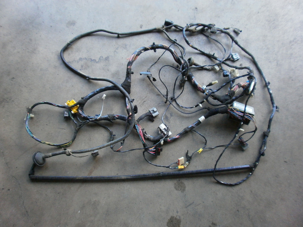
Replacing a wiring harness in a Jeep Wrangler is a significant undertaking, but with the right knowledge and tools, it's a project a capable DIYer can tackle. This guide aims to provide a comprehensive understanding of Wrangler wiring harnesses, covering everything from their purpose and components to troubleshooting and safety considerations. We'll also explain how to read and interpret a wiring diagram, a crucial skill for this task.
Purpose of a Wrangler Wiring Harness Diagram
A wiring harness diagram is essentially a roadmap of your Jeep's electrical system. It's a visual representation of how all the electrical components are interconnected. This diagram is invaluable for several reasons:
- Repairing Faults: When electrical problems arise, the diagram helps you trace circuits, identify faulty wires, and pinpoint the source of the issue.
- Performing Modifications: If you're adding aftermarket accessories like lights, winches, or stereos, the diagram is essential for understanding how to integrate them into the existing electrical system safely and correctly.
- Understanding the System: Even if you're not currently facing a problem, studying the diagram can help you gain a deeper understanding of how your Jeep's electrical system functions.
- Harness Replacement: When corrosion, damage or rodent infestation happens, you may need to replace your entire harness. A wiring diagram is essential for ensuring you connect everything correctly to avoid causing more damage.
Key Specs and Main Parts of a Wrangler Wiring Harness
A modern Wrangler's wiring harness is a complex network of wires, connectors, and protective coverings. Here's a breakdown of the key specs and main parts:
- Wire Gauge (AWG): Wire gauge refers to the thickness of the wire. Different circuits require different wire gauges based on the amount of current they carry. Thicker wires (lower AWG numbers) are used for high-current circuits like the starter motor, while thinner wires (higher AWG numbers) are used for low-current circuits like interior lights.
- Wire Insulation: The wires are insulated with a variety of materials, typically PVC or cross-linked polyethylene (XLPE). XLPE is more resistant to heat and abrasion, making it a better choice for engine bay harnesses.
- Connectors: Connectors provide a way to easily connect and disconnect wiring harnesses. They come in various shapes and sizes, each designed for a specific application. Common connector types include:
- Deutsch Connectors: Known for their durability and weather resistance, often used in off-road vehicles.
- Weatherpack Connectors: Another type of weather-resistant connector commonly found in automotive applications.
- Multi-pin Connectors: These connectors bundle multiple wires into a single connection point.
- Fuse Box(es): The fuse box houses fuses and relays, which protect the electrical circuits from overcurrents and control various electrical components.
- Grounding Points: Grounding points provide a connection to the vehicle's chassis, allowing current to return to the battery. Proper grounding is crucial for the correct operation of all electrical components.
- Main Harness Sections:
- Engine Harness: Connects the engine sensors, actuators, and other components to the vehicle's electrical system.
- Dashboard Harness: Connects the instrument cluster, switches, and other components in the dashboard to the vehicle's electrical system.
- Body Harness: Connects the lights, door locks, and other components in the body to the vehicle's electrical system.
Understanding Wiring Diagram Symbols
Wiring diagrams use a standardized set of symbols to represent electrical components and connections. Here's a quick guide to some of the most common symbols:
- Lines: Represent wires. The thickness of the line may indicate the wire gauge (though this isn't always the case). Dashed lines often represent wires within a specific module or harness.
- Colors: Wires are often color-coded to help identify them. For example, a red wire might be used for power, while a black wire might be used for ground. The wiring diagram will include a color code legend.
- Circles: Can represent various components, sometimes depending on what's inside the circle.
- Resistors: Represented by a jagged line.
- Capacitors: Represented by two parallel lines.
- Ground: Represented by a symbol that looks like a downward-pointing tree or a series of decreasing horizontal lines.
- Fuses: Represented by a zigzag line inside a rectangle, or a straight line through a rectangle.
- Relays: Represented by a coil and a set of contacts. The coil is energized to close the contacts, completing the circuit.
- Switches: Represented by a break in the line that can be opened or closed to control the flow of current.
- Connectors: Represented by interlocking shapes or symbols showing pins and sockets.
How a Wrangler Wiring Harness Works
The wiring harness acts as the central nervous system of your Jeep. It distributes power from the battery and alternator to all the electrical components, and it carries signals between sensors and control modules. For example, when you turn on the headlights, the switch sends a signal to the body control module (BCM), which then activates the headlight relay. The relay then closes the circuit, allowing power to flow to the headlights. Each circuit is protected by a fuse or circuit breaker, which will interrupt the flow of current if there's an overload or short circuit.
Modern Wranglers use a CAN (Controller Area Network) bus system. Instead of each component having its own dedicated wire to every other component, many share data over a few data lines. This reduces wiring complexity and weight. Modules like the PCM (Powertrain Control Module), BCM, and ABS module communicate with each other over this bus.
Real-World Use: Basic Troubleshooting Tips
Here are some basic troubleshooting tips for common wiring harness issues:
- Start with the Obvious: Check fuses first. A blown fuse is often the cause of electrical problems. Consult your owner's manual or the fuse box diagram to identify the correct fuse.
- Use a Multimeter: A multimeter is an essential tool for diagnosing electrical problems. You can use it to check for voltage, continuity, and resistance.
- Check Ground Connections: Poor ground connections can cause a variety of electrical problems. Make sure all ground connections are clean, tight, and free of corrosion.
- Look for Damaged Wires: Inspect the wiring harness for signs of damage, such as cuts, abrasions, or melted insulation. Rodent damage is a common culprit.
- Test for Shorts: A short circuit occurs when a wire comes into contact with ground. You can use a multimeter to test for shorts by checking for continuity between a wire and the vehicle's chassis.
- Use a Test Light: A test light can be used to quickly check for power and ground at various points in the circuit.
For Example: If your tail lights aren't working, start by checking the tail light fuse. If the fuse is good, use a multimeter to check for voltage at the tail light connector. If there's no voltage, trace the circuit back to the BCM or the tail light switch, checking for damaged wires or connectors along the way. If you have voltage at the BCM output, but no voltage at the tail light connector, then you know to investigate the wiring between them.
Safety Considerations
Working with electrical systems can be dangerous. Here are some important safety precautions to keep in mind:
- Disconnect the Battery: Always disconnect the negative battery cable before working on any electrical components. This will prevent accidental short circuits and electrical shocks.
- Be Aware of the Airbag System: The airbag system is a high-voltage system that can be dangerous if mishandled. Consult your service manual before working on any components near the airbags.
- Avoid Working in Wet Conditions: Water and electricity don't mix. Never work on electrical systems in wet conditions.
- Wear Safety Glasses: Protect your eyes from sparks and debris.
- Use Insulated Tools: Use tools with insulated handles to prevent electrical shock.
- High-Risk Components: Pay special attention to the starter solenoid and the alternator. These components carry high current and can be dangerous if shorted out. Similarly, any wiring related to the airbag system should be approached with extreme caution. Incorrect handling can cause the airbags to deploy, resulting in serious injury.
Replacing a wiring harness is a complex process, so it's critical to take your time and follow the instructions carefully. Using the wiring diagram, you can trace each wire and connector, ensuring that everything is connected correctly.
We have a detailed wiring diagram file available for download. This diagram will provide you with the specific information you need to tackle your Wrangler wiring harness replacement project effectively. Having access to the right information can significantly simplify the process and ensure successful outcomes.