
Jeep Xj Air Conditioning System Diagram
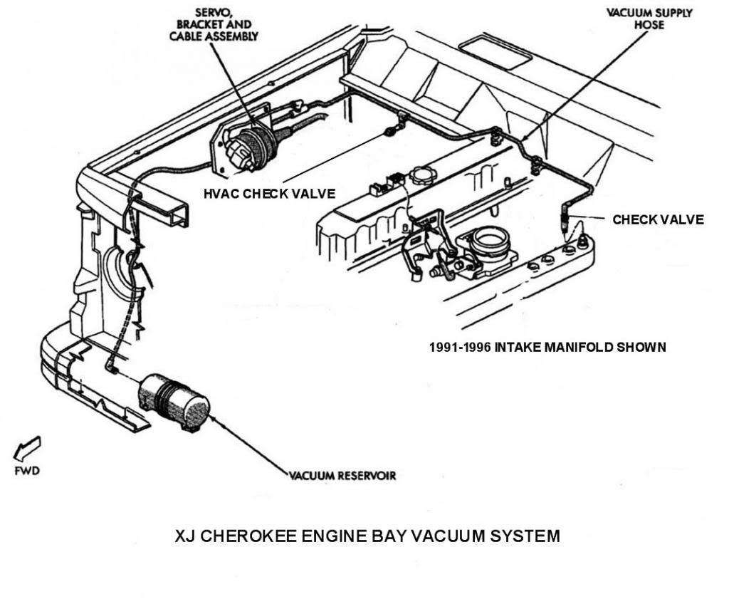
Understanding the air conditioning (AC) system in your Jeep XJ is crucial for effective maintenance, troubleshooting, and even modifications. This article provides a detailed overview of the Jeep XJ AC system diagram, breaking down its components, function, and practical applications. Think of this as a deep dive into the blueprints of your XJ's cooling capabilities.
Purpose of Understanding the XJ AC System Diagram
Why bother learning about the AC system diagram? Several compelling reasons exist:
- Diagnosis and Repair: Identifying malfunctioning components becomes significantly easier when you understand the system's layout. The diagram guides you directly to the potential problem area.
- Parts Replacement: Knowing the specific names and locations of parts, as indicated on the diagram, prevents ordering the wrong components.
- System Modifications: If you're considering upgrading the AC system for better performance or converting to R134a refrigerant, the diagram provides a solid foundation for planning your modifications.
- Preventative Maintenance: Understanding the system allows for proactive maintenance, preventing costly breakdowns down the road.
- Educational Value: Simply put, gaining a comprehensive understanding of how your vehicle operates is empowering.
Key Specifications and Main Parts
The XJ's AC system, regardless of model year, follows a basic vapor-compression refrigeration cycle. Here are the core components:
- Compressor: The heart of the system. It compresses the refrigerant gas, raising its temperature and pressure. Driven by the engine's accessory belt.
- Condenser: Located in front of the radiator, the condenser cools the high-pressure refrigerant gas, converting it into a high-pressure liquid.
- Receiver-Drier (Accumulator): Filters debris and removes moisture from the refrigerant. It also acts as a reservoir for liquid refrigerant. Later models often use an accumulator located on the low-pressure side.
- Expansion Valve (Orifice Tube): This metering device regulates the flow of refrigerant into the evaporator. The expansion valve is located at the evaporator inlet, while the orifice tube is within the liquid line.
- Evaporator: Located inside the vehicle, the evaporator absorbs heat from the cabin air, causing the liquid refrigerant to evaporate into a low-pressure gas. This process cools the air blowing through the vents.
- Refrigerant Lines: High-pressure and low-pressure lines connect all the components, carrying the refrigerant throughout the system.
- Pressure Switches: These switches monitor the refrigerant pressure and control the compressor, protecting the system from damage due to over- or under-pressure.
- Blower Motor: Circulates air through the evaporator core and into the passenger cabin.
Understanding Diagram Symbols
AC system diagrams use specific symbols to represent components and connections. Here’s a breakdown:
- Lines: Solid lines typically represent high-pressure refrigerant lines, while dashed lines represent low-pressure lines.
- Arrows: Indicate the direction of refrigerant flow.
- Boxes and Circles: These represent individual components like the compressor, condenser, evaporator, and receiver-drier/accumulator. The specific shape and shading may vary depending on the diagram.
- Electrical Symbols: Represent wiring connections, relays, fuses, and switches associated with the AC system's electrical controls.
- Colors: While not always present, color coding can help differentiate between high-pressure and low-pressure lines, or different sections of the electrical wiring.
Common Line Styles and Their Meanings
- Solid Line: Represents a physical connection, typically a refrigerant line.
- Dashed Line: Usually indicates a low-pressure refrigerant line or a vacuum line.
- Dotted Line: Can represent a signal wire or a control line within the electrical system.
How the AC System Works: A Simplified Explanation
The AC system operates on the principle of heat transfer through refrigerant. Here's a simplified breakdown:
- Compression: The compressor compresses the refrigerant gas, increasing its pressure and temperature.
- Condensation: The hot, high-pressure refrigerant flows to the condenser, where it cools down and changes into a high-pressure liquid, releasing heat to the environment.
- Metering: The high-pressure liquid refrigerant passes through the expansion valve (or orifice tube), which reduces its pressure and regulates its flow into the evaporator. This process causes the liquid refrigerant to partially vaporize.
- Evaporation: The cold, low-pressure refrigerant enters the evaporator core. As warm air from the cabin is blown across the evaporator fins, the refrigerant absorbs heat, causing it to completely evaporate into a low-pressure gas. This process cools the air, which is then blown into the cabin.
- Return: The low-pressure refrigerant gas returns to the compressor, completing the cycle.
Real-World Use: Basic Troubleshooting Tips
The AC system diagram is invaluable when troubleshooting AC problems. Here are a few basic tips:
- No Cold Air: Check the compressor clutch engagement. If the clutch isn't engaging, look for electrical issues (fuses, relays, pressure switches). The diagram can guide you to the relevant components. If the clutch is engaging, the system may be low on refrigerant or have a blockage.
- Weak Airflow: Ensure the blower motor is functioning correctly and that there are no obstructions in the air ducts.
- Strange Noises: Identify the source of the noise. If it's coming from the compressor, it could indicate a problem with the compressor itself. The diagram helps you confirm its location and connections.
- Leaks: Refrigerant leaks are often visible as oily residue. Use the diagram to trace the refrigerant lines and identify potential leak locations.
Safety Precautions
Working on AC systems involves risks. Always keep these points in mind:
- Refrigerant Handling: Refrigerant can cause frostbite and is harmful to the environment. Never release refrigerant into the atmosphere. Have the system professionally evacuated before disconnecting any lines.
- High Pressure: The AC system operates at high pressures. Always depressurize the system before disconnecting any components.
- Electrical Components: Disconnect the negative battery cable before working on any electrical components of the AC system.
- Professional Assistance: If you're not comfortable working on the AC system, consult a qualified technician.
Highlighting Risky Components
The compressor and the high-pressure lines are particularly risky. The compressor contains pressurized refrigerant and moving parts, and the high-pressure lines carry refrigerant at extremely high pressures, which can cause serious injury if ruptured. Also be careful of the receiver drier. It contains chemicals for moisture removal which can cause irritation. Always wear gloves and eye protection.
By understanding the XJ AC system diagram and its components, you'll be well-equipped to tackle basic troubleshooting, maintenance, and even system upgrades. Always remember safety precautions and consult a professional when needed. This knowledge empowers you to keep your XJ cool and comfortable for years to come.
We have a downloadable version of the Jeep XJ AC system diagram available. Contact us to receive the file and further enhance your understanding.