
John Deere Zero Turn Drive Belt Diagram
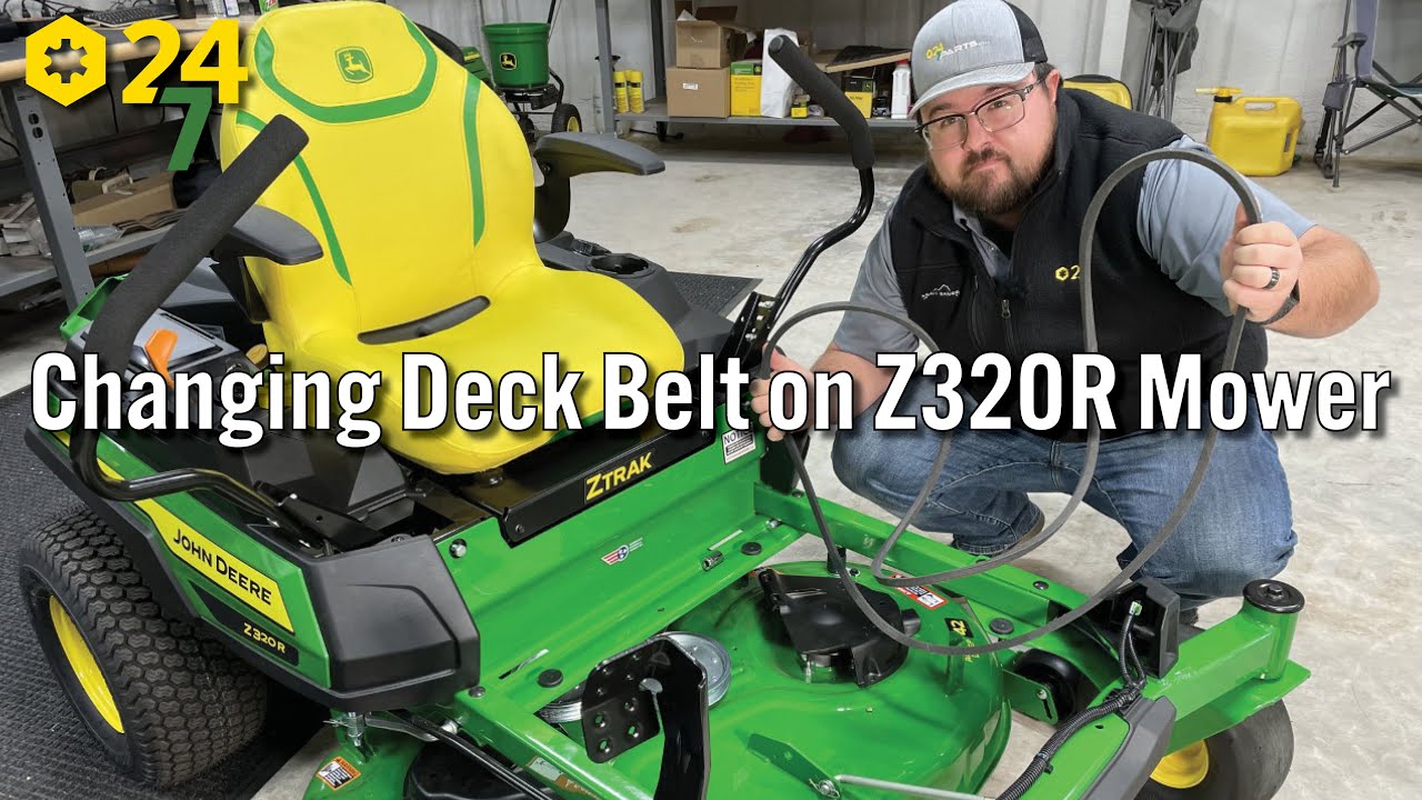
So, you're looking to tackle a drive belt replacement or just gain a deeper understanding of your John Deere zero-turn mower? Excellent! Knowing your way around the drive system is crucial for efficient maintenance and preventing costly downtime. This guide will walk you through a typical John Deere zero-turn drive belt diagram, providing the knowledge you need to confidently work on your machine. We’ll break down the diagram, explain the key components, and offer practical troubleshooting tips.
Purpose of the Drive Belt Diagram
Why bother with a diagram in the first place? Well, a John Deere zero-turn's drive system is more complex than a simple lawnmower. These machines use a sophisticated arrangement of belts and pulleys to deliver independent power to each wheel, allowing for that characteristic zero-degree turning radius. The diagram is your roadmap for this system, vital for:
- Repairs: Identifying the correct belt routing after replacement is critical. An improperly routed belt can cause premature wear, slippage, or even complete failure.
- Maintenance: Understanding the belt's path helps you inspect it for wear, cracks, or glazing, allowing for proactive replacement.
- Troubleshooting: A squealing belt, loss of drive power, or uneven cutting can often be traced back to issues within the drive system. The diagram helps you pinpoint the problem area.
- Learning: Gaining a solid grasp of how the drive system functions will make you a more confident and capable DIY mechanic.
Key Specs and Main Parts
Before diving into the diagram itself, let's familiarize ourselves with the essential components:
- Engine Pulley: This pulley is directly connected to the engine's crankshaft and provides the rotational power for the entire system.
- Hydrostatic Transmissions (Hydro Pumps): Zero-turns don't use a traditional transmission. Instead, they employ two independent hydrostatic transmissions, one for each wheel. These transmissions use hydraulic fluid to transfer power.
- Hydrostatic Transmission Pulleys: These pulleys are connected to the input shafts of the hydrostatic transmissions. The drive belt(s) transfer power from the engine pulley to these pulleys.
- Idler Pulleys: These pulleys don't directly drive anything but are crucial for maintaining proper belt tension and routing the belt around obstructions.
- Tensioner Pulley: A spring-loaded or manually adjustable pulley that applies consistent tension to the drive belt(s), preventing slippage and ensuring optimal performance. This is often a critical wear point.
- Drive Belt(s): The heart of the system, these belts transfer power from the engine to the hydrostatic transmissions. John Deere often uses high-quality Kevlar-reinforced belts for durability.
Typical specifications you might find related to the drive belt(s) include:
- Belt Length: Crucial for proper fit. Usually measured in inches. Using the wrong length belt can lead to slippage or excessive tension, shortening its lifespan.
- Belt Width: Another important dimension. Using a belt that's too narrow might cause it to slip deeper into the pulley grooves, leading to premature wear.
- Belt Type: Look for belts designed specifically for mower applications. These belts are typically reinforced for high-stress environments.
Understanding the Symbols in the Diagram
Drive belt diagrams aren't always straightforward. Here's a breakdown of common symbols you might encounter:
- Solid Lines: These typically represent the main drive belt(s). The thickness of the line can sometimes indicate the belt's width.
- Dashed Lines: Often used to show the belt path behind other components or to indicate the belt's "return" path.
- Arrows: Indicate the direction of belt travel. Pay close attention to these; incorrect routing can be disastrous.
- Circles: Represent pulleys. Smaller circles are usually idler pulleys, while larger circles are typically engine or hydrostatic transmission pulleys.
- Icons: Some diagrams use small icons to represent specific components, such as the engine, hydrostatic transmissions, or tensioner spring. Refer to the diagram's legend for clarification.
- Color Coding: While less common on older diagrams, some modern diagrams may use color coding to differentiate between multiple belts or highlight specific sections of the drive system. Always refer to the diagram's key for color definitions.
How the Drive System Works
The engine's rotational power is transferred to the engine pulley. From there, the drive belt(s) transmit this power to the hydrostatic transmission pulleys. Each hydrostatic transmission independently controls the speed and direction of one of the rear wheels. When you move the control levers, you're essentially adjusting the hydraulic flow within the transmissions, thereby varying the speed and direction of each wheel.
The idler pulleys guide the belt around obstructions and maintain the correct wrap angle on the driven pulleys (hydrostatic transmission pulleys). The tensioner pulley ensures that the belt remains tight, preventing slippage and maintaining optimal power transfer.
Zero-turn mowers often employ either a single-belt or dual-belt system. A single-belt system uses one long belt that snakes its way around all the pulleys. A dual-belt system, on the other hand, uses two shorter belts, each driving one of the hydrostatic transmissions. Dual-belt systems are often found on larger or more powerful mowers.
Real-World Use: Basic Troubleshooting Tips
Here are a few common problems and how the drive belt diagram can help you diagnose them:
- Squealing Belt: This often indicates a loose belt. Check the tensioner pulley and make sure it's applying sufficient pressure. Use the diagram to verify the correct belt routing and ensure the tensioner is positioned correctly. A worn or glazed belt can also squeal, requiring replacement.
- Loss of Drive Power: If one or both wheels have lost power, the belt(s) may be broken or severely worn. Consult the diagram to inspect the belt's condition and routing. Also, examine the pulleys for damage.
- Uneven Cutting: While this can be caused by other factors (e.g., blade issues), a slipping drive belt can sometimes contribute to uneven cutting. Use the diagram to confirm proper belt tension and routing.
- Vibration: Excessive vibration can be a sign of a damaged pulley or a belt that's out of alignment. The diagram can help you visually inspect the pulleys for wobble or damage and ensure the belt is running true.
Before making any adjustments, always disconnect the spark plug wire to prevent accidental starting!
Safety Considerations
Working on the drive system can be hazardous if proper precautions aren't taken. Keep these points in mind:
- Rotating Parts: The engine pulley, hydrostatic transmission pulleys, and idler pulleys rotate at high speeds when the engine is running. Keep hands and clothing clear of these components at all times.
- Hot Surfaces: The engine and hydrostatic transmissions can become very hot during operation. Allow them to cool down before working on the drive system.
- Spring Tension: The tensioner pulley is often spring-loaded, and the spring can exert considerable force. Use caution when removing or adjusting the tensioner. Wear eye protection.
- Hydraulic Fluid: Be aware that hydrostatic transmissions contain hydraulic fluid under pressure. If you suspect a leak in the transmission, consult a qualified technician.
Always consult your John Deere operator's manual for specific safety instructions and recommendations.
By understanding the drive belt diagram and the function of each component, you'll be well-equipped to diagnose and repair common issues with your John Deere zero-turn mower. This knowledge empowers you to save money on repairs and keep your machine running smoothly for years to come.
We have a high-resolution, downloadable version of a sample John Deere Zero Turn Drive Belt Diagram available. Contact us for access – it's a valuable resource!