
Jvc Car Stereo Wiring Harness Diagram
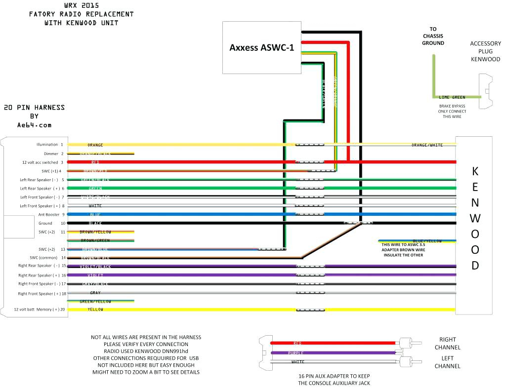
Welcome, fellow gearheads! Let's dive into the wonderful (and sometimes confusing) world of JVC car stereo wiring harness diagrams. Whether you're replacing a blown fuse, installing a new head unit, or simply trying to decipher why your bass sounds like a washing machine full of rocks, understanding these diagrams is absolutely crucial. Think of it as the Rosetta Stone for your car audio system. This article will provide you with the necessary knowledge to confidently tackle your next car audio project. We will also highlight potential safety hazards and provide troubleshooting tips.
Why You Need a JVC Car Stereo Wiring Harness Diagram
The purpose of a wiring harness diagram is multifaceted. Primarily, it serves as a visual guide showing the precise connections between the car's electrical system and the JVC car stereo. This is invaluable for:
- Repairs: Identifying damaged or incorrectly wired connections.
- Installation: Ensuring correct wiring when installing a new head unit, speakers, or amplifier.
- Troubleshooting: Diagnosing problems like a stereo that won't turn on, distorted sound, or blown fuses.
- Learning: Understanding how the car's electrical system interacts with the audio system.
- Customization: Making safe and informed modifications to the audio system.
Without a diagram, you're essentially working blind. Guessing which wire goes where can lead to short circuits, damage to the stereo or the car's electrical system, and a whole lot of frustration. Trust me, a little time spent studying the diagram is far better than a headache (and potentially a hefty repair bill) down the road.
Key Specs and Main Parts
Before we dissect the diagram itself, let's cover the basics. The JVC wiring harness diagram typically depicts the following:
- Power Wires:
- +12V Constant (Battery): This wire provides constant power to the stereo, allowing it to retain memory settings (radio presets, equalizer settings, etc.). It's usually yellow and connected directly to the car's battery via a fuse.
- +12V Switched (Ignition): This wire provides power only when the ignition is turned on. It's usually red and connected to a circuit that's active only when the key is in the "ACC" or "ON" position. This wire turns the stereo on and off with the car.
- Ground: This wire completes the circuit, providing a return path for the electricity. It's usually black and connected to the car's chassis or a dedicated ground point. A good ground is essential for proper operation.
- Speaker Wires: These wires connect the head unit to the speakers. There are usually four pairs of wires, one pair for each speaker (front left, front right, rear left, rear right). Each pair consists of a positive (+) and a negative (-) wire, often identified by different colors or a stripe on one of the wires. Incorrect polarity can result in thin sound and poor bass response.
- Remote Turn-On Wire (Amplifier): This wire signals an external amplifier to turn on when the head unit is powered on. It's usually blue or blue with a white stripe.
- Antenna Wire: Connects to the car's antenna for radio reception.
- Illumination Wire: Dims the stereo's display when the headlights are turned on. Usually orange or orange with a white stripe.
- Other Wires: Depending on the specific JVC model, there might be additional wires for features like steering wheel controls, parking brake input (for video playback), or reverse gear input (for backup cameras).
Decoding the Diagram: Symbols, Colors, and Lines
Understanding the symbols, colors, and lines used in the diagram is critical. Let's break it down:
- Lines: Lines represent wires. Their thickness might indicate the wire gauge (thicker lines = thicker wires, capable of carrying more current).
- Colors: Each wire is represented by a specific color. Common colors include yellow, red, black, white, green, blue, and orange. Refer to the color code key on the diagram. Some wires may have a stripe of a different color, further differentiating them. For example, "Blue/White" indicates a blue wire with a white stripe.
- Symbols:
- Fuse: A small rectangle with a wavy line through it. Indicates a fuse.
- Ground: A series of descending lines connected to a point.
- Connector: A rectangular shape representing a plug or connector.
- Speaker: A circle with a cone inside.
- Battery: A symbol representing the car battery.
- Switch: A symbol indicating a switch (e.g., ignition switch).
The diagram will also include text labels identifying each wire and its function. Pay close attention to these labels. The diagram might also provide voltage and current ratings for certain circuits. For example: "12V/10A" means the circuit operates at 12 volts and is protected by a 10-amp fuse.
How It Works: The Electrical Flow
The basic principle is simple: electrical current flows from the battery, through the stereo, and back to the battery (through the ground wire). The ignition wire acts as a switch, controlling the flow of current to the stereo when the ignition is turned on. The speaker wires carry the amplified audio signal from the head unit to the speakers. The remote turn-on wire triggers the amplifier to power on and off in sync with the head unit.
Understanding this flow is crucial for troubleshooting. For example, if the stereo won't turn on, the problem could be a blown fuse in the +12V constant or +12V switched circuit, a bad ground connection, or a faulty ignition switch.
Real-World Use: Basic Troubleshooting Tips
Here are a few common issues and how a wiring diagram can help:
- Stereo won't turn on: Check the +12V constant and +12V switched fuses. Verify the ground connection is secure and making good contact with the chassis. Use a multimeter to test for voltage at the +12V constant and +12V switched wires.
- No sound from speakers: Check the speaker wire connections. Make sure the polarity is correct (+ and - connected correctly). Test the speakers themselves to ensure they are not blown.
- Distorted sound: Check the speaker wire connections for shorts or loose connections. Make sure the speakers are not overloaded (too much power).
- Blown fuses: Identify the circuit that's blowing the fuse and check for shorts or overloaded circuits. A common cause is a speaker wire shorting to ground.
Important Note: Always disconnect the negative terminal of the car battery before working on the electrical system. This will prevent accidental short circuits and potential damage.
Safety: Proceed with Caution!
Working with car electrical systems can be dangerous if proper precautions are not taken. The +12V constant wire carries a significant amount of current and can cause a severe shock or fire if shorted to ground. Always disconnect the battery before working on any electrical components. Use insulated tools and avoid working in wet conditions.
Modifying the wiring harness can void your car's warranty. If you are not comfortable working with electrical systems, it is best to consult a qualified professional.
Never bypass a fuse with a higher amperage fuse. This could overload the circuit and cause a fire.
Always double-check your wiring before reconnecting the battery. Incorrect wiring can damage the stereo, the car's electrical system, or both.
Remember, safety first! A little caution goes a long way in preventing accidents and ensuring a successful installation or repair.
Now you're armed with the knowledge to tackle your JVC car stereo wiring project. Remember to always refer to the specific wiring diagram for your JVC model, as wiring configurations can vary.
We have the wiring diagrams in PDF format, so that you have them available when you need them. Download the diagram, save it and print for easier access when needed.