
Kawasaki Starter Solenoid Wiring Diagram
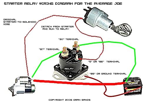
Understanding the Kawasaki starter solenoid wiring diagram is crucial for diagnosing and repairing electrical issues related to your motorcycle's starting system. Whether you're performing routine maintenance, troubleshooting a no-start condition, or customizing your bike's electrical system, this knowledge is invaluable. We'll break down the diagram, explaining its components, function, and how to use it for practical troubleshooting.
Purpose of the Wiring Diagram
A wiring diagram is essentially a roadmap of your motorcycle's electrical system, specifically focused on the starter solenoid and its associated circuits. It shows the connections between various components, wire colors, and their functions. This allows you to:
- Diagnose Starting Problems: Pinpoint the exact cause of a no-start or intermittent starting issue.
- Perform Repairs: Identify and replace faulty wires, connectors, or components.
- Understand Circuit Function: Gain a deeper understanding of how the starting system operates.
- Customize Electrical Systems: Safely add or modify electrical components while avoiding shorts or damage.
Key Specs and Main Parts
The starter solenoid wiring diagram will typically include the following key components:
- Battery: The power source for the entire electrical system. Voltage is typically 12V DC.
- Starter Motor: The electric motor that cranks the engine. It requires a large current to operate.
- Starter Solenoid: An electromagnetic switch that allows the high-current circuit to the starter motor to be controlled by a low-current signal from the start button. This component is the lynchpin of the starting system.
- Start Button (or Switch): The handlebar-mounted switch that initiates the starting process.
- Ignition Switch: The switch that enables the entire electrical system.
- Fuses: Protective devices that prevent damage from overcurrents. Always use the correct amperage fuse to protect the circuit.
- Wiring Harness: A bundle of wires that connects all the components. Each wire is typically color-coded.
- Ground Connections: Connections to the frame or engine, providing a return path for current. Good ground connections are essential for reliable operation.
- Diode(s): Used in some starting circuits to prevent back-feeding of current into other circuits.
Symbols: Deciphering the Diagram
Understanding the symbols used in the wiring diagram is crucial for proper interpretation:
- Lines: Represent wires. Thicker lines often indicate wires carrying higher current.
- Colors: Wires are color-coded for identification. Common colors include Red (power), Black (ground), Yellow, Green, Blue, and White. A legend on the diagram will define the specific color codes for your Kawasaki model.
- Circles/Dots: Represent connections or splices between wires.
- Rectangles: Often used to represent components like the starter solenoid, ignition switch, or start button.
- Zigzag Lines: Typically indicate resistors.
- Coil Symbol: Represents the solenoid coil.
- Ground Symbol: Indicates a connection to the vehicle's chassis (ground).
- Fuse Symbol: Indicates a fuse, with the amperage rating often indicated nearby.
For example, a solid red line might represent the main power wire from the battery to the ignition switch. A black line connected to the frame with a ground symbol signifies a ground connection.
How It Works: The Starting Sequence
Here's a simplified explanation of how the starting system functions:
- Ignition On: When you turn the ignition switch to the "ON" position, power is supplied to the motorcycle's electrical system.
- Start Button Pressed: Pressing the start button completes a low-current circuit that energizes the solenoid coil within the starter solenoid.
- Solenoid Activation: The energized solenoid coil creates a magnetic field, pulling an internal plunger or switch.
- High-Current Connection: The plunger connects the high-current circuit between the battery and the starter motor.
- Starter Motor Engages: The starter motor receives power and begins to crank the engine.
- Engine Starts: Once the engine starts, you release the start button, breaking the low-current circuit, and the solenoid de-energizes, disconnecting the high-current circuit.
The starter solenoid acts as an intermediary, allowing the low-current start button to control the high-current flow to the starter motor. Without the solenoid, the start button and its associated wiring would need to handle the extremely high current required by the starter, making it impractical and potentially dangerous.
Real-World Use: Basic Troubleshooting
Here are some basic troubleshooting steps using the wiring diagram:
- No Cranking: If the starter motor doesn't crank at all, check the battery voltage first. Then, use a multimeter to check for voltage at the starter solenoid's input terminal (from the battery). If voltage is present, check for voltage at the output terminal when the start button is pressed. If there's no voltage at the output terminal when the start button is pressed, the solenoid is likely faulty.
- Clicking Sound: A clicking sound from the solenoid usually indicates a weak battery, poor connections, or a failing solenoid. Clean and tighten all battery terminals and ground connections. If the problem persists, the solenoid may need replacement.
- Blown Fuses: Repeatedly blowing fuses indicates a short circuit. Use the wiring diagram to trace the affected circuit and look for damaged wires or components. Common culprits include chafed wiring harnesses or faulty electrical accessories.
- Intermittent Starting: Intermittent starting problems can be caused by loose connections, corroded terminals, or a failing solenoid. Carefully inspect all connections and clean them as needed.
Always refer to your specific Kawasaki model's wiring diagram for accurate troubleshooting.
Safety: Important Precautions
Working with electrical systems can be dangerous. Here are some important safety precautions:
- Disconnect the Battery: Before working on any electrical component, disconnect the negative (-) battery terminal to prevent accidental shorts and electric shock.
- Use Insulated Tools: Use tools with insulated handles to minimize the risk of electric shock.
- Avoid Working in Wet Conditions: Never work on electrical systems in wet or damp environments.
- Know Your Limits: If you're not comfortable working with electrical systems, consult a qualified mechanic.
- The Battery and Starter Motor Circuits are High Current: The battery circuit and starter motor circuits carry very high current. Accidental shorts can cause sparks, burns, and even fires. Be extremely cautious when working on these circuits.
Remember that the starter solenoid itself contains a coil that, when energized, stores energy. While generally safe, improper handling or accidental shorts could cause arcing.
Disclaimer: This article provides general information and should not be considered a substitute for professional advice. Always consult a qualified mechanic for specific repairs or modifications.
We have access to a vast library of Kawasaki starter solenoid wiring diagrams. Contact us to obtain the diagram specific to your motorcycle model.