Kia Telluride Trailer Wiring Harness
So, you're looking to understand the Kia Telluride's trailer wiring harness. Maybe you're installing one yourself, troubleshooting an existing connection, or just want to get a better grasp of your vehicle's electrical system. Whatever your reason, understanding the wiring harness is crucial for safe and reliable towing. This article will break down the key components, wiring diagram, and troubleshooting tips you need to know.
Purpose of Understanding the Telluride Trailer Wiring Harness
Why bother diving into the intricacies of this wiring harness? Several reasons. First and foremost is safety. Improper wiring can lead to trailer light malfunctions, which are dangerous and illegal. A faulty connection could also interfere with your Telluride's electrical system, potentially causing damage. Second, understanding the harness allows for informed repairs and modifications. If a light fails, knowing the wiring scheme enables you to pinpoint the problem and fix it quickly. Finally, grasping the diagram is essential for installing a trailer brake controller, which is a must for heavier trailers. Understanding the harness empowers you to work on your vehicle confidently and safely.
Key Specs and Main Parts
Let's get down to brass tacks. The Kia Telluride typically uses a 7-way RV-style connector for its trailer wiring. However, some models might come with a 4-way flat connector as a base, requiring an adapter for 7-way functionality. The 7-way connector provides connections for:
- Ground (White): Establishes a common ground between the vehicle and the trailer.
- Tail/Running Lights (Brown): Powers the taillights, side marker lights, and license plate light on the trailer.
- Left Turn/Brake (Yellow): Activates the left turn signal and brake light on the trailer.
- Right Turn/Brake (Green): Activates the right turn signal and brake light on the trailer.
- Auxiliary/12V Power (Black): Provides a 12V DC power source for trailer accessories like interior lights or a battery charger.
- Electric Brakes (Blue): Sends a signal to the trailer's electric brakes, controlled by a brake controller in the vehicle. This is the critical wire for safety.
- Reverse Lights (Purple): Activates the reverse lights on the trailer when the vehicle is in reverse.
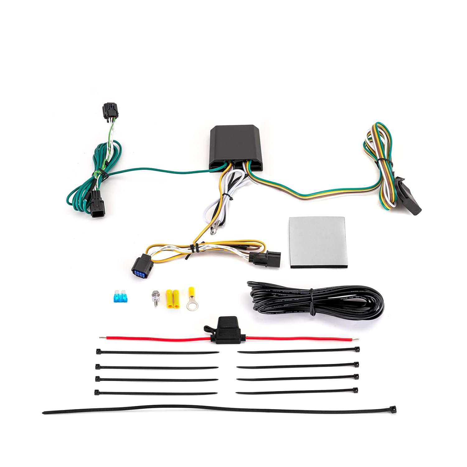
The main parts involved include the 7-way connector itself, the wiring harness that runs from the connector to the vehicle's electrical system, and any associated fuses or relays. These components are often located near the trailer hitch receiver, typically under the rear bumper.
Understanding Wiring Diagram Symbols
Deciphering a wiring diagram can seem daunting, but it's simpler than it looks once you understand the basic symbols. The wiring diagram illustrates the connections between these components. Let’s break down the elements:
- Solid Lines: Represent wires. The thickness of the line doesn't necessarily indicate wire gauge.
- Dashed Lines: Often indicate a wire harness or a connection that is hidden or runs behind another component.
- Circles or Squares with Numbers/Letters: Represent connectors. The number or letter identifies the specific connector.
- Resistor Symbol (Zig-zag line): Indicates a resistor in the circuit.
- Ground Symbol (Stacked horizontal lines): Represents the ground connection.
- Fuse Symbol (A squiggly line with a box around it): Indicates a fuse, a safety device that protects the circuit from overcurrent.
- Relay Symbol: Typically shown as a coil with a switch that it controls.
- Color Codes: Wires are often identified by color codes (e.g., WH for white, BK for black, RD for red). The diagram should include a key to these color codes.
The color of the wire is extremely important. Always double-check that the wire colors match the diagram before making any connections. A wrong connection can damage your vehicle's electrical system.
How It Works: A Circuit-Based Explanation
The trailer wiring harness essentially extends the vehicle's lighting and braking circuits to the trailer. When you turn on your headlights, the tail light circuit in your Telluride sends power through the brown wire to the trailer's tail lights. Similarly, when you activate the turn signals or brakes, the corresponding circuits in the Telluride send power through the yellow (left) and green (right) wires to the trailer's turn and brake lights. The white wire provides a common ground for all circuits.
The blue wire (electric brakes) is a bit different. It's connected to a brake controller in the vehicle. The brake controller senses when you apply the brakes and sends a proportional amount of power through the blue wire to the trailer's electric brakes. The auxiliary power wire (black) provides a constant 12V DC power source, which can be used to charge a trailer battery or power other accessories.
Real-World Use: Troubleshooting Tips
Let's say your trailer lights aren't working. Here's a basic troubleshooting approach:
- Check the connections: Ensure all connections are clean, tight, and free of corrosion. Use dielectric grease to protect connections from moisture.
- Check the fuses: Locate the fuses related to the trailer wiring (consult your owner's manual) and check if any are blown. Replace any blown fuses with the correct amperage rating.
- Test the vehicle-side connector: Use a circuit tester or multimeter to check if the vehicle is sending power to the correct pins on the 7-way connector when the corresponding lights or brakes are activated.
- Test the trailer-side connector: Similarly, test the trailer-side connector to see if it's receiving power from the vehicle.
- Inspect the wiring: Look for any damaged or frayed wires on both the vehicle and the trailer. Repair or replace any damaged wiring.
- Ground issues: Grounding problems are very common causes of lighting issues. Make sure your ground connection to the frame is solid and free of corrosion. Consider adding an additional ground strap if problems persist.
- Isolate the problem: If possible, try connecting the trailer to another vehicle to see if the problem is with the trailer or the Telluride.
Safety Considerations
Working with automotive electrical systems can be dangerous. Always disconnect the negative battery cable before working on any wiring.
Warning: The auxiliary power (black) and electric brake (blue) wires carry significant current. Exercise extreme caution when working with these circuits. Incorrect wiring could result in short circuits, electrical fires, or damage to your vehicle's electrical system.
Use proper crimping tools and connectors to ensure secure and reliable connections. Avoid using wire nuts or other non-automotive connectors. Always double-check your work before reconnecting the battery. If you are unsure about any aspect of the wiring, consult a qualified mechanic.
Remember, if dealing with the electric brake circuit, an improperly installed or malfunctioning brake controller can have serious consequences. Invest in a quality brake controller and follow the manufacturer's instructions carefully.
The information provided here is a general guide. Always refer to the specific wiring diagram for your Kia Telluride model year. If you are unsure about any aspect of the wiring, consult a qualified mechanic.
We have a detailed wiring diagram available for download. This diagram provides a visual representation of the trailer wiring harness, including wire colors, connector locations, and fuse assignments. This will be an invaluable resource during your repair or installation process.