Lawn Mower Starter Solenoid Wiring Diagram
So, you're tackling a lawn mower starter solenoid issue? Excellent! Understanding the wiring diagram is absolutely crucial for successful repairs, modifications, or even just basic troubleshooting. Think of the solenoid as the electrical gatekeeper for your lawnmower's starting system. This article breaks down that gate, showing you exactly how it works and how to fix it when it doesn't.
Why Bother with a Solenoid Wiring Diagram?
Why spend time understanding a diagram when you can just replace parts? Well, diagrams are invaluable for a few key reasons:
- Accurate Diagnosis: Blindly replacing parts is costly and inefficient. The diagram helps pinpoint the exact problem area. Is it the solenoid itself, the wiring, the battery connection, or something else?
- Safe Repairs: Working with electrical systems can be dangerous. Understanding the wiring ensures you're not inadvertently short-circuiting something or creating a fire hazard.
- Modifications & Upgrades: Thinking about adding a kill switch or upgrading your starting system? The diagram is your roadmap.
- Learning and Understanding: Simply put, understanding how the system *should* work helps you understand when it *isn't* working.
Key Specs and Main Parts of a Lawn Mower Starter Solenoid System
Let's break down the core components involved. While specific wiring can vary slightly based on the model of lawn mower, the principles are the same.
- Battery: Provides the primary electrical power (typically 12V). A fully charged battery is essential.
- Ignition Switch: Also known as the starter switch. This is what you turn to initiate the starting sequence.
- Solenoid: An electromechanical switch. It uses a small electrical signal from the ignition switch to control a much larger current to the starter motor. Think of it as a relay designed for high amperage.
- Starter Motor: The device that physically turns the engine's flywheel to start the combustion process.
- Ground Connection: A critical connection that completes the electrical circuit. A good, clean ground is essential for proper operation.
- Fuses (and sometimes a relay): Provide circuit protection. These can be located in the power wire or in the control wire.
Key specs you might encounter include the solenoid's voltage rating (usually 12V), its current rating (the maximum amperage it can handle), and the terminal types. Some solenoids use threaded studs, while others use spade connectors. Make sure any replacement is compatible with your existing wiring.
Decoding the Wiring Diagram: Lines, Colors, and Symbols
A wiring diagram isn't as daunting as it looks once you understand the basic language:
- Lines: Represent wires. The thickness of the line may or may not indicate the wire gauge (diameter). Thicker lines generally indicate wires carrying higher current.
- Colors: Each wire is typically color-coded (e.g., Red for positive, Black for ground, Yellow for ignition). The diagram will have a legend explaining the color codes. Always double-check the color against the actual wire. Colors can fade or be misidentified.
- Symbols: Standard electrical symbols are used to represent components. Common symbols include:
- Battery: A series of long and short parallel lines.
- Switch: A break in a line that can be closed (on) or open (off).
- Solenoid: A coil symbol with a switch.
- Starter Motor: A circle with an "M" inside.
- Fuse: A zigzag line inside a rectangle.
- Ground: A series of downward-pointing triangles.
Important Tip: Many diagrams use abbreviations. Look for a legend that defines terms like "IGN" (ignition), "GND" (ground), "BAT" (battery), and "STR" (starter).
How the Lawn Mower Starter Solenoid System Works
Here’s a simplified explanation of how it all comes together:
- Turning the Key: When you turn the ignition switch, you're completing a circuit that sends a small electrical signal to the solenoid's coil.
- Activating the Solenoid: The electrical current flowing through the solenoid coil creates a magnetic field. This magnetic field pulls a plunger (a movable metal core) inside the solenoid.
- Closing the Circuit: The plunger movement closes a set of heavy-duty contacts *inside* the solenoid. This creates a direct, high-current connection between the battery and the starter motor.
- Starting the Engine: The starter motor, now receiving a large amount of current, engages with the engine's flywheel and turns the engine over.
- Releasing the Key: Once the engine starts, you release the ignition switch. This breaks the circuit to the solenoid coil, the magnetic field collapses, the plunger returns to its original position, and the high-current connection to the starter motor is broken.
Real-World Use: Basic Troubleshooting Tips
Okay, so the mower isn’t starting. Where do you begin?
- No Clicking Sound: If you don't hear any clicking when you turn the key, the problem is likely in the ignition switch, the wiring to the solenoid, or the solenoid itself. Check the fuse, if there is one. Use a multimeter to verify that voltage is reaching the solenoid's small control terminals when the key is turned. If not, trace the wiring back to the ignition switch and battery.
- Clicking Sound, But No Starting: A "click" usually means the solenoid is engaging, but the high-current circuit isn't completing. This could indicate a bad solenoid (the contacts inside are worn), a poor battery connection, a bad ground, or a problem with the starter motor itself. Use a multimeter to check the voltage at the starter motor while the key is turned. If you have battery voltage, the starter motor is likely the culprit.
- Solenoid "Chattering": This rapid clicking and unclicking often indicates a low battery voltage. The solenoid is engaging, but the voltage drops too low to hold it in place. Charge the battery or test its capacity.
- Check the Ground: A poor ground connection can cause all sorts of strange issues. Make sure the ground wire from the battery to the frame (and from the engine to the frame) is clean and securely fastened. Use sandpaper to clean any corrosion.
Important: Before testing any electrical components, disconnect the spark plug wire to prevent accidental starting.
Safety First: Working with the Starting System
Working on a lawn mower's electrical system presents several potential hazards:
- Battery Acid: Batteries contain corrosive acid. Wear eye protection and gloves when handling batteries.
- Electrical Shock: While 12V systems are generally considered low-voltage, short circuits can generate significant heat and sparks, potentially causing burns or fires. Always disconnect the battery negative terminal before working on the electrical system.
- Accidental Starting: As mentioned earlier, disconnect the spark plug wire to prevent the engine from starting accidentally while you're working on it.
- Fuel Leaks: Be mindful of fuel lines and the carburetor. Avoid creating sparks near fuel.
Never work on the electrical system if you're tired, distracted, or unsure of what you're doing. If you're not comfortable troubleshooting electrical issues, seek the help of a qualified mechanic.
Understanding your lawn mower's starter solenoid wiring diagram isn't just about fixing problems; it's about gaining a deeper understanding of how your machine works. With this knowledge, you'll be better equipped to maintain your mower, diagnose problems accurately, and even make performance upgrades.
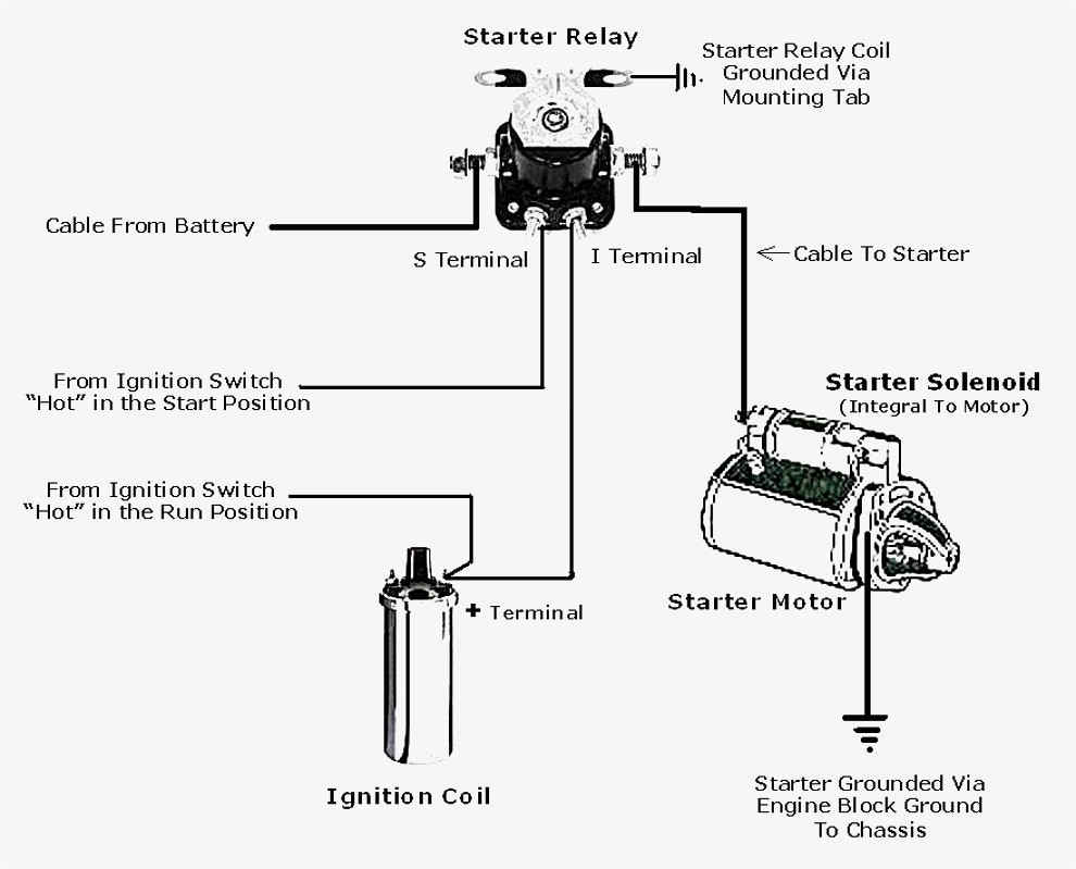
We have a generic starter solenoid wiring diagram available for download, which will provide a visual reference for the concepts discussed in this article. It's a great tool to have on hand when troubleshooting or planning repairs.