Layout 2005 Chrysler 300 Fuse Box Diagram
Alright folks, let's dive into the fuse box diagram for a 2005 Chrysler 300. Understanding this diagram is absolutely crucial, whether you're troubleshooting a faulty component, adding aftermarket accessories, or just trying to understand the electrical system of your car. Think of it as the electrical roadmap for your 300. Without it, you're navigating blindly.
Purpose: Your Electrical Lifeline
Why bother learning about this diagram? Simple. It's your go-to resource for diagnosing and resolving electrical issues. Specifically, a fuse box diagram helps you:
- Identify blown fuses: The most common use. Quickly pinpoint the fuse responsible for a specific circuit.
- Troubleshoot electrical problems: If a component isn't working (e.g., headlights, radio, power windows), the diagram helps you trace the circuit and isolate the problem.
- Install aftermarket accessories: When adding things like amplifiers, lighting, or security systems, you need to tap into the electrical system safely and correctly. The diagram shows you which circuits are suitable and where to connect.
- Understand the electrical system: It provides a clear overview of how the various electrical components are connected and protected.
Key Specs and Main Parts of the 2005 Chrysler 300 Fuse Box
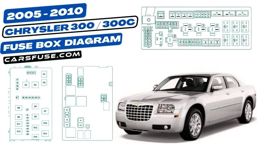
The 2005 Chrysler 300 typically has two main fuse box locations:
- Underhood Fuse Box (Power Distribution Center - PDC): Located in the engine compartment, this houses high-amperage fuses and relays that protect major systems like the engine, transmission, and braking system. It's the main distribution point for power throughout the vehicle.
- Interior Fuse Box (Junction Block): Typically located inside the cabin, often under the dashboard or in the glove compartment area. This one protects lower-amperage circuits related to interior components like lights, radio, power windows, and other accessories.
Each location contains:
- Fuses: These are sacrificial devices that protect electrical circuits from overcurrent. They contain a thin metal strip that melts and breaks the circuit when the current exceeds a certain limit.
- Relays: Electrically operated switches that control high-current circuits using a low-current signal. They are often used to control things like headlights, starter motors, and air conditioning compressors.
- Circuit Breakers: Similar to fuses, but resettable. They interrupt the circuit when an overcurrent is detected, but can be reset manually or automatically once the fault is cleared. Not as common as fuses in the 300.
- Connectors: Provide connection points for wiring harnesses and other electrical components.
The diagram itself is a schematic representation of these components and their interconnections. It will include labels for each fuse, relay, and connector, along with their corresponding circuit functions and amperage ratings.
Understanding the Symbols: Deciphering the Code
The fuse box diagram uses a variety of symbols to represent different components and connections. Here's a breakdown of common symbols:
- Fuses: Typically represented by a small, rectangular box with a number inside indicating the amperage rating (e.g., "10" for a 10-amp fuse).
- Relays: Usually shown as a square or rectangle with internal symbols indicating the coil and contact connections. They may have labels like "Headlight Relay" or "Fuel Pump Relay."
- Wires: Represented by lines. Line thickness *might* (but usually doesn't on these diagrams) indicate wire gauge, but focus on the color.
- Grounds: Usually depicted as a series of decreasing horizontal lines or a triangle pointing downward.
- Connectors: Shown as circles or squares with numbers indicating the pin connections.
Color Coding: Wiring diagrams use color-coded lines to indicate the wire's insulation color. Common colors include:
- Red: Often indicates a power wire (positive voltage).
- Black: Typically indicates a ground wire (negative voltage).
- Other Colors (Blue, Green, Yellow, White, etc.): Represent specific circuit functions. The diagram will include a legend that explains the meaning of each color. For example, a yellow wire might be for the turn signals, while a blue wire might be for the headlights.
Numerical Labels: Each fuse, relay, and connector is assigned a number. These numbers are referenced in the diagram's legend, which provides information about the component's function, amperage rating, and location. For example, "Fuse F25 - Radio (15A)" indicates that fuse number 25, rated at 15 amps, protects the radio circuit.
How It Works: Tracing the Circuit
The fuse box diagram illustrates how electricity flows through the car's electrical system. It shows the path from the battery, through the fuses and relays, to the various electrical components. When troubleshooting, you can use the diagram to trace the circuit and identify potential points of failure.
For example, let's say your headlights aren't working. Here's how you might use the diagram:
- Locate the headlight circuit: Find the section of the diagram that deals with the headlights.
- Identify the fuse and relay: Note the fuse and relay that protect and control the headlights. The diagram will show their location and amperage rating.
- Check the fuse: Visually inspect the fuse to see if it's blown. If it is, replace it with a fuse of the same amperage rating.
- Test the relay: If the fuse is good, test the headlight relay. You can use a multimeter to check for voltage at the relay terminals or swap it with a known good relay to see if that solves the problem.
- Trace the wiring: If both the fuse and relay are good, use the diagram to trace the wiring from the fuse box to the headlights, looking for any breaks, shorts, or loose connections.
Real-World Use: Basic Troubleshooting Tips
Here are some practical troubleshooting tips using the fuse box diagram:
- Start with the obvious: Always check the fuse first. A blown fuse is the most common cause of electrical problems.
- Use a test light or multimeter: These tools are essential for checking for voltage and continuity in the circuit.
- Check for shorts to ground: A short to ground occurs when a wire comes into contact with the vehicle's metal chassis. This can cause a fuse to blow repeatedly.
- Look for loose connections: Loose connections can cause intermittent electrical problems. Check all connectors and terminals to make sure they are securely fastened.
- Don't increase fuse amperage: Never replace a fuse with one of a higher amperage rating. This can overload the circuit and cause a fire.
Safety First: Highlighting Risky Components
Working with automotive electrical systems can be dangerous. Here are some safety precautions to keep in mind:
- Disconnect the battery: Before working on any electrical circuit, disconnect the negative battery cable to prevent accidental shocks or short circuits.
- Work in a well-ventilated area: Some electrical components can produce harmful fumes.
- Use insulated tools: To prevent electric shock, use tools with insulated handles.
- Be careful around airbags: Airbags are triggered by electrical signals. Mishandling them can cause them to deploy unexpectedly. The airbag fuse is usually very clearly marked, and it's *highly* recommended you disconnect the battery and wait several minutes before doing *anything* near the airbag system.
- High-Amperage Circuits: Be especially cautious when working with high-amperage circuits, such as the starter motor or alternator. These circuits can deliver a powerful electric shock.
Important note: Always refer to the vehicle's service manual for specific wiring diagrams and troubleshooting procedures. The information provided here is for general guidance only.
Understanding the 2005 Chrysler 300 fuse box diagram is an invaluable skill for any car owner or DIY mechanic. By familiarizing yourself with the symbols, locations, and troubleshooting techniques, you'll be well-equipped to tackle a wide range of electrical problems. Remember to always prioritize safety and consult the service manual when in doubt.
We have the full, high-resolution fuse box diagram for your 2005 Chrysler 300 ready for download. Feel free to grab a copy and keep it handy for future reference!