
Light Switch Wiring Diagram With Neutral
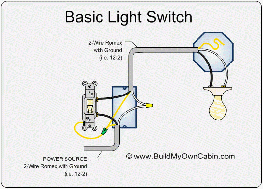
Hey there, gearheads and DIY enthusiasts! Let's dive into the world of household electrical wiring, specifically focusing on a light switch wiring diagram with a neutral wire. Understanding this circuit is crucial not just for repairs, but also for safely modifying or upgrading your home's electrical system. Think of it like understanding the fuel injection system in your car – once you grasp the fundamentals, troubleshooting and even making improvements becomes far less daunting.
Purpose: Why This Diagram Matters
Why bother learning about a light switch wiring diagram? Well, several reasons jump to mind:
- Repairing faulty switches: A flickering light or a switch that doesn't work is a common problem. Understanding the wiring allows you to diagnose whether the switch itself is bad or if the issue lies elsewhere in the circuit.
- Replacing old switches: Upgrading to modern switches, like dimmers or smart switches, requires knowing how the existing switch is wired to ensure proper installation.
- Adding new light fixtures: If you're expanding your lighting, understanding the basics lets you plan the wiring and make sure you're not overloading circuits.
- General Electrical Knowledge: Just like knowing how your car's engine works helps you understand performance upgrades, understanding basic electrical circuits helps you appreciate the bigger picture of your home's power system.
- Safety: Most importantly, understanding the wiring diagram will help you work safely with electricity, avoiding nasty shocks or even fires.
Key Specs and Main Parts
Before we jump into the diagram, let's define some key components:
- Hot (or Live) Wire: This wire carries the electrical current from the power source (the breaker panel). It's typically black in color. This is the wire you need to respect above all others.
- Neutral Wire: This wire provides a return path for the current back to the power source. It's typically white in color. It's connected to the neutral busbar in your breaker panel.
- Ground Wire: This wire provides a safety path for current in case of a fault (like a short circuit). It's typically green or bare copper. It's connected to the grounding busbar in your breaker panel, which is connected to a grounding rod buried outside your house.
- Switch: The switch is the electromechanical device that opens or closes the circuit, controlling the flow of electricity to the light fixture. We're focusing on a simple single-pole, single-throw (SPST) switch here, which is the most common type.
- Light Fixture: This is the light itself, including the bulb or LED and the housing.
- Junction Box: This is a metal or plastic box where electrical wires are joined together. All connections *must* be inside a junction box for safety.
- Wire Connectors (Wire Nuts): These are plastic caps used to securely connect two or more wires together. Proper wire nuts and connections are crucial.
Symbols: Deciphering the Diagram
Electrical diagrams use standard symbols to represent components. Here's a breakdown of what you'll typically see:
- Straight Lines: Represent wires. Thicker lines might indicate heavier-gauge wires, but usually it's just for visual clarity.
- Solid Lines: Usually mean the wire is visible in the diagram.
- Dotted Lines: Might indicate the wire is hidden or running behind a wall.
- Switch Symbol: Often looks like a break in the line with a lever arm to indicate the switch mechanism. The lever arm moves to connect or disconnect the circuit.
- Light Fixture Symbol: Can vary, but often looks like a circle with a cross inside or a bulb shape.
- Junction Box Symbol: Usually represented as a rectangle or square.
- Wire Colors: Key! Black is hot, white is neutral, green (or bare) is ground. Following color conventions is essential for safety and proper function. Never assume a wire is a specific color without verifying with a multimeter.
In a wiring diagram with a neutral, you'll see:
The hot wire (black) coming from the breaker panel entering the junction box.
The neutral wire (white) coming from the breaker panel entering the junction box.
The ground wire (green or bare) coming from the breaker panel entering the junction box.
How It Works: Following the Current
Here's the fundamental flow of electricity in this circuit:
- The hot wire carries current from the breaker panel to the junction box.
- From the junction box, the hot wire runs to one terminal of the light switch.
- Another wire (often black, sometimes another color but *never* white or green) runs from the other terminal of the switch to the light fixture. This is called the "switch leg".
- The neutral wire runs directly from the breaker panel (through the junction box) to the light fixture. It provides the return path for the current.
- The ground wire also runs from the breaker panel (through the junction box) to the light fixture and often to the metal box holding the switch. It's there for safety.
When the switch is in the "on" position, it closes the circuit, allowing current to flow from the hot wire, through the switch, through the wire to the light fixture, through the bulb, and back to the breaker panel via the neutral wire. When the switch is "off", it breaks the circuit, stopping the flow of current and turning off the light.
Real-World Use: Basic Troubleshooting Tips
Here are some common problems and how the wiring diagram can help:
- Light Doesn't Turn On:
- Check the breaker. Is it tripped? Reset it if so.
- Use a multimeter to check for voltage at the switch terminals (with the switch "on"). If there's no voltage, the problem is upstream (closer to the breaker panel).
- If there *is* voltage at the switch but the light still doesn't work, the switch itself might be bad. Use the multimeter to check for continuity across the switch terminals when it's in the "on" position. No continuity means a bad switch.
- Check the light bulb itself!
- Light Stays On:
- The switch might be stuck in the "on" position. Try replacing the switch.
- Less likely, there could be a short circuit somewhere in the wiring. This is more dangerous and requires careful investigation. Consult a qualified electrician.
- Flickering Light:
- Loose connections are the most common cause. Check all wire connections in the junction box and at the light fixture, ensuring they are tight and secure.
- A failing light bulb can also cause flickering.
Safety: Respect the Electrons!
Electricity can be dangerous! Here are some crucial safety precautions:
- Always turn off the power at the breaker panel before working on any electrical wiring. Verify the power is off with a non-contact voltage tester or a multimeter.
- Never work on electrical wiring if you are wet or standing in water.
- Use insulated tools.
- Wear safety glasses.
- Double-check your wiring before restoring power. Make sure all connections are secure and that wires are properly insulated.
- If you are unsure about anything, consult a qualified electrician. Don't risk your safety or damage to your home.
- The hot (black) wires and the circuit breaker itself are the most dangerous components. Respect them!
- Ensure all wiring meets local electrical codes. These codes are in place to protect you and your property.
Understanding a light switch wiring diagram with a neutral is a valuable skill for any homeowner. It empowers you to perform basic repairs, upgrade your lighting, and, most importantly, work safely with electricity. Remember to always prioritize safety and consult a qualified electrician when in doubt.
We have a detailed PDF wiring diagram available for download. It provides a clear visual representation of the circuit and includes helpful annotations.