Location Throttle Position Sensor Diagram
Let's dive into the inner workings of your vehicle's throttle position sensor (TPS). We're going to break down the TPS diagram, a crucial resource for anyone tackling engine diagnostics, modifications, or even routine maintenance. This isn't just some abstract schematic; it's the key to understanding how your engine's computer "knows" how much you're pressing the accelerator pedal, and therefore, how much power you're requesting.
Purpose of the TPS Diagram
Why should you bother understanding a TPS diagram? Simple. Think of it as the roadmap to resolving throttle-related issues. Whether your car is experiencing poor acceleration, erratic idle, stalling, or even transmission shifting problems (many modern automatics rely on TPS data), the TPS is a prime suspect. Having access to, and understanding, the diagram allows you to:
- Diagnose problems accurately: Pinpoint wiring faults, sensor failures, or connection issues.
- Perform repairs confidently: Replace a faulty TPS, repair damaged wiring, or adjust the sensor.
- Understand your engine's control system: Gain a deeper understanding of how the engine control unit (ECU) interprets driver input and controls engine output.
- Modify or upgrade your engine: Fine-tune fuel and ignition maps based on accurate TPS readings after modifications like throttle body upgrades.
Key Specs and Main Parts
Before we dissect the diagram itself, let's identify the key components associated with the TPS:
- Throttle Position Sensor (TPS): The main sensor itself. Typically a potentiometer or hall-effect sensor. A potentiometer is a variable resistor that changes resistance based on the throttle plate angle. A hall-effect sensor uses a magnetic field to detect the throttle position, offering greater reliability and precision.
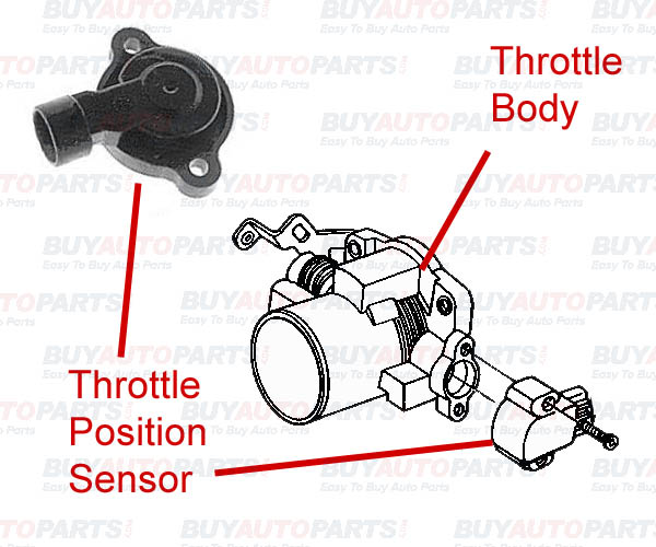
- Throttle Body: The housing that contains the throttle plate. The TPS is mounted on the throttle body and directly connected to the throttle plate shaft.
- Electrical Connector: The connector that plugs into the TPS, providing power, ground, and a signal wire.
- Wiring Harness: The wires that connect the TPS to the ECU and the vehicle's electrical system.
- Engine Control Unit (ECU): The brain of the engine. It receives the TPS signal and uses it to control fuel injection, ignition timing, and other engine parameters.
Key specifications you might find in a TPS diagram (or supporting documentation) include:
- Voltage Range: The expected voltage output of the TPS at various throttle positions (e.g., 0.5V at closed throttle, 4.5V at wide-open throttle).
- Resistance Range: (For potentiometer-type sensors) The total resistance of the potentiometer and the resistance at specific throttle positions.
- Pin Assignments: Which wire in the connector corresponds to power, ground, and signal.
- Connector Type: The specific type of connector used, allowing for correct replacement or repair.
Symbols: Decoding the Diagram
Understanding the symbols in a TPS diagram is essential for interpreting the information. Here's a breakdown of common symbols:
- Solid Lines: Represent wires. The thickness of the line might indicate wire gauge.
- Dashed Lines: Often indicate shielding or grounding paths.
- Arrows: Show the direction of current flow.
- Resistor Symbol (Zigzag Line): Represents the potentiometer within the TPS.
- Ground Symbol (Downward Pointing Triangles): Indicates a connection to the vehicle's chassis ground.
- Voltage Source Symbol (Plus and Minus): Shows the source of power for the TPS, typically a 5V reference voltage from the ECU.
- Connector Symbols (Squares or Rectangles with Pins): Depict the electrical connectors. Numbers or letters near the pins indicate the pin assignments.
- Color Codes: Wires are often color-coded (e.g., Red for power, Black for ground, Green for signal). The diagram will usually include a color key.
Color codes are particularly important. For example, if the diagram shows that the signal wire should be a yellow wire with a blue stripe, you can quickly identify the correct wire on the TPS connector.
How It Works
The TPS diagram shows the electrical circuit that allows the ECU to determine the throttle plate's position. Here's how it typically works:
- The ECU provides a 5V reference voltage to the TPS.
- The TPS acts as a voltage divider, using the potentiometer or hall-effect sensor.
- As the throttle plate opens, the resistance of the potentiometer (or the magnetic field sensed by the hall-effect sensor) changes.
- This change in resistance alters the voltage signal sent back to the ECU.
- The ECU reads this voltage signal and interprets it as a specific throttle position. For instance, 0.5V might represent closed throttle, while 4.5V represents wide-open throttle.
The ECU then uses this throttle position information to control fuel injection, ignition timing, and other engine parameters, optimizing engine performance based on the driver's input.
Real-World Use: Basic Troubleshooting Tips
The TPS diagram is your best friend when troubleshooting throttle-related issues. Here are a few common problems and how the diagram helps:
- Faulty Wiring: Use the diagram to trace the wires from the TPS connector to the ECU. Look for breaks, shorts, or corrosion. A multimeter can be used to check continuity and voltage at different points in the circuit.
- Bad TPS Sensor: Use the diagram to identify the power, ground, and signal wires. With the ignition on (but the engine not running), backprobe the connector (carefully insert a thin probe alongside the wire) and measure the voltage at the signal wire. Slowly open and close the throttle. The voltage should change smoothly and linearly, without any sudden jumps or drops. If it doesn't, the TPS sensor is likely faulty. Compare reading with specification on diagram.
- Incorrect TPS Adjustment: Some TPS sensors are adjustable. The diagram may show the correct voltage or resistance setting for the closed-throttle position. Use a multimeter to adjust the sensor until the voltage or resistance is within the specified range. Note: Not all TPS sensors are adjustable, and attempting to adjust a non-adjustable sensor can damage it.
- ECU Problems: While less common, the ECU can be the source of TPS-related problems. If you've ruled out wiring and sensor issues, the ECU might be the culprit. Consult the diagram to verify the ECU's input pins for the TPS signal.
Important: Always double-check your wiring and connections against the diagram. Incorrect wiring can damage the TPS, the ECU, or other components.
Safety
Working with electrical systems can be dangerous. Here are some safety precautions to keep in mind:
- Disconnect the Battery: Before working on any electrical components, disconnect the negative terminal of the battery to prevent shorts and electrical shocks.
- Use Proper Tools: Use insulated tools designed for automotive electrical work.
- Avoid Working in Wet Conditions: Water and electricity don't mix. Work in a dry environment.
- Be Careful with Backprobing: When backprobing connectors, be extremely careful not to short any wires together.
- ECU Caution: The ECU is a sensitive electronic device. Handle it with care and avoid static electricity.
- High Voltage Components: Be especially cautious around the ignition system (ignition coils, spark plugs), as these components can carry high voltage even with the engine off.
The TPS diagram is a powerful tool for understanding and troubleshooting your vehicle's throttle control system. By familiarizing yourself with the symbols, components, and wiring, you can confidently diagnose and repair throttle-related issues, improve your engine's performance, and gain a deeper understanding of automotive technology. Remember always to prioritize safety and double-check your work.
We have a comprehensive TPS diagram file available for download to further assist you. It contains detailed schematics, pinouts, and troubleshooting tips. This document will provide the necessary insight to fix those common issues and even diagnose obscure errors. Contact us for access.