Ls 2-wire Temp Sensor Wiring Diagram
Alright, let's dive into the world of 2-wire temperature sensors and their wiring diagrams. This isn't some esoteric black magic; it's a fundamental piece of automotive (and other machinery) diagnostics and repair. Whether you're tracking down a pesky check engine light, upgrading your engine management system, or simply trying to understand how your car *really* works, understanding this is essential.
Purpose of Understanding the 2-Wire Temp Sensor Diagram
Why bother learning about a 2-wire temp sensor wiring diagram? There are several key reasons:
- Troubleshooting: When your engine's running rough, throwing codes related to coolant temperature (ECT), intake air temperature (IAT), or oil temperature, a wiring problem is often the culprit. The diagram helps you trace the circuit and pinpoint breaks, shorts, or corrosion.
- Repair & Replacement: Replacing a faulty sensor is straightforward, but understanding the wiring is crucial. You need to know where the wires connect and whether there are any potential issues with the harness. Incorrect wiring can damage the new sensor or, worse, the ECU (Engine Control Unit).
- Modifications & Upgrades: When installing aftermarket sensors or data logging systems, you'll need to integrate them into the existing wiring. A diagram provides the information necessary to do this safely and correctly. Imagine installing an aftermarket boost gauge that needs an accurate temperature reading - the 2-wire sensor becomes critical.
- Learning & Understanding: Simply put, understanding how a sensor's wiring fits into the bigger picture deepens your knowledge of how your vehicle works. This knowledge empowers you to diagnose and fix problems yourself, saving you money and giving you a greater appreciation for your machine.
Key Specs and Main Parts
Let's break down the essential components and specifications involved in a typical 2-wire temperature sensor setup:
Key Specs:
- Temperature Range: The operating range of the sensor (e.g., -40°C to 150°C). This range dictates the sensor's suitability for specific applications.
- Resistance Curve: This is the *heart* of the sensor. It describes the relationship between the sensor's resistance and the temperature it's measuring. This curve is crucial for the ECU to accurately interpret the sensor's signal. It's usually a Negative Temperature Coefficient (NTC) thermistor, meaning resistance decreases as temperature increases.
- Accuracy: How close the sensor's reading is to the actual temperature. This is usually expressed as a percentage (e.g., ±1% accuracy).
- Sensor Type: Usually a thermistor, specifically an NTC (Negative Temperature Coefficient) thermistor. These are robust and relatively inexpensive.
- Connector Type: The specific type of connector used to attach the sensor to the wiring harness (e.g., Metri-Pack, Weather Pack).
Main Parts:
- Temperature Sensor: The device that measures the temperature and changes its resistance accordingly.
- Wiring Harness: The collection of wires that connect the sensor to the ECU and other components.
- Connectors: The plugs that connect the sensor to the wiring harness. Corrosion here is a common problem.
- ECU (Engine Control Unit): The "brain" of the engine management system. It receives the sensor's signal, interprets it based on the resistance curve, and uses this information to adjust fuel injection, ignition timing, and other parameters.
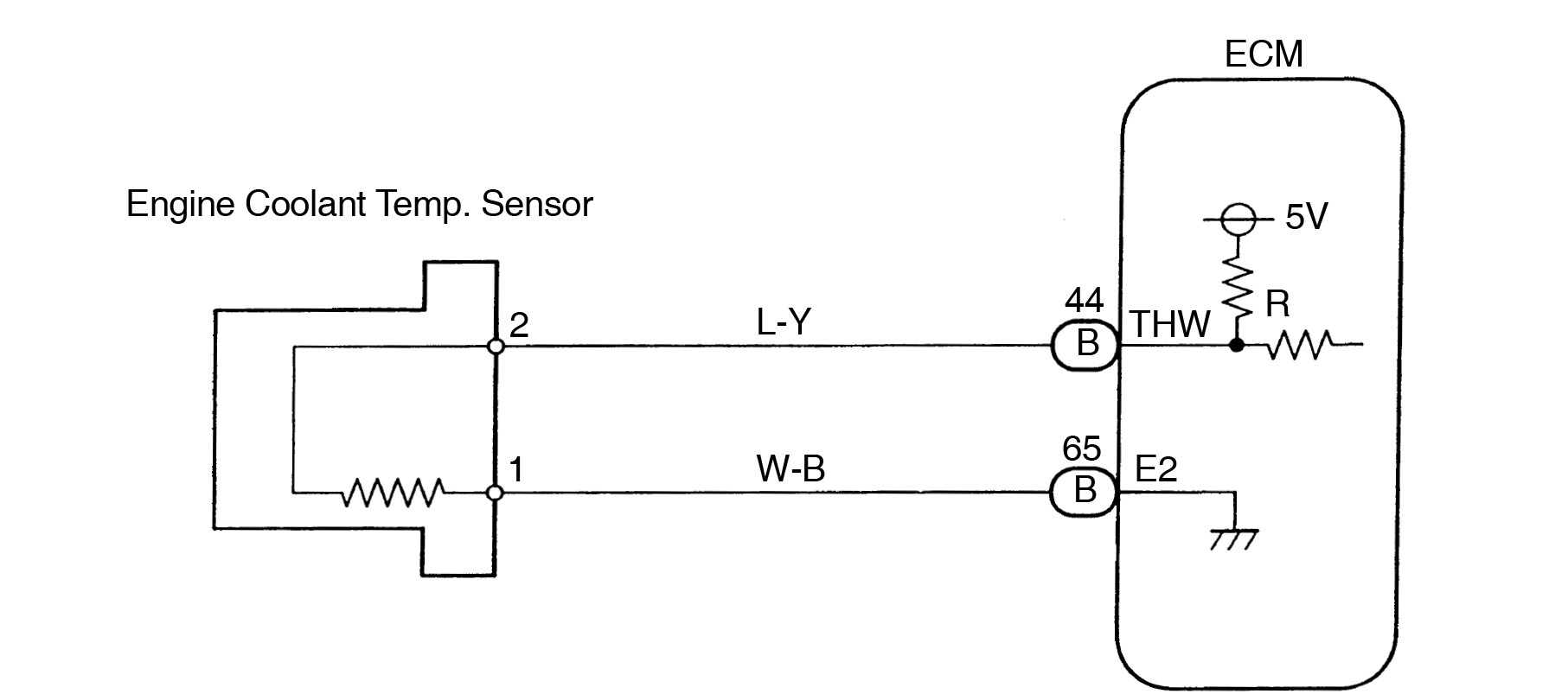
- Resistor (Pull-up resistor): Frequently, one wire will run to the ECU, and the other will run to Ground. However, another common configuration is one wire running to the ECU signal pin, and the other wire running to a +5V reference voltage through a pull-up resistor. This pull-up resistor ensures that the ECU sees a valid voltage signal even when the sensor resistance is high (low temperature).
Symbols in the Wiring Diagram
Wiring diagrams use standardized symbols to represent components and connections. Understanding these symbols is key to reading the diagram correctly:
- Solid Lines: Represent wires. Thicker lines may indicate power wires.
- Dashed Lines: Often represent shielded wires or CAN bus lines (though CAN bus usually has more than two wires).
- Circles with Numbers: Represent connectors. The number indicates the pin number within the connector.
- Resistor Symbol (Zig-Zag Line): Represents a resistor, often the pull-up resistor. The value of the resistor (e.g., 2.2kΩ) is usually indicated near the symbol.
- Ground Symbol (Stacked Triangles): Indicates a connection to the vehicle's chassis ground.
- ECU Symbol (Rectangle): Represents the ECU. The pins connected to the sensor are usually labeled.
- Color Codes: Wires are often identified by color codes (e.g., "BLU" for blue, "GRN" for green). This is *critical* for tracing wires.
Important note: Wiring diagrams from different manufacturers may use slightly different symbols, but the basic principles remain the same. Always refer to the specific diagram for your vehicle.
How It Works
The operation of a 2-wire temperature sensor circuit is relatively straightforward:
- The temperature sensor, which is essentially a thermistor, changes its resistance based on the surrounding temperature.
- The sensor is connected to the ECU via two wires.
- One wire is typically connected to a 5V reference voltage through a pull-up resistor *within the ECU*. The other wire is connected to the ECU's signal input pin and ultimately leads to a path to ground.
- As the sensor's resistance changes, it alters the voltage drop across the pull-up resistor, changing the voltage at the ECU's signal pin.
- The ECU measures this voltage and uses the sensor's resistance curve (stored in its memory) to determine the actual temperature.
- The ECU then uses this temperature information to adjust engine parameters. For example, a cold engine requires a richer fuel mixture, so the ECU will increase the fuel injector pulse width based on the coolant temperature sensor's reading.
Essentially, the 2-wire sensor acts as a variable resistor, allowing the ECU to "read" the temperature as a voltage signal.
Real-World Use – Basic Troubleshooting Tips
Here are some practical troubleshooting tips for a 2-wire temperature sensor:
- Check for Codes: Use an OBD-II scanner to check for diagnostic trouble codes (DTCs) related to the sensor (e.g., P0116, P0117, P0118 for coolant temperature sensor issues).
- Visual Inspection: Examine the sensor, wiring, and connectors for any signs of damage, corrosion, or loose connections. Pay close attention to the connector pins.
- Resistance Measurement: Disconnect the sensor and use a multimeter to measure its resistance. Compare the measured resistance to the sensor's resistance curve at a known temperature (e.g., ambient temperature). A significantly different resistance indicates a faulty sensor.
- Voltage Measurement: With the sensor connected and the ignition on, use a multimeter to measure the voltage at the ECU's signal pin. The voltage should change as the sensor's temperature changes. A steady voltage, regardless of temperature, suggests a wiring problem or a faulty ECU.
- Continuity Test: Use a multimeter to perform a continuity test on the wiring between the sensor and the ECU. This will help identify any breaks or shorts in the wiring.
- Wiring Diagram is Key: Refer to the wiring diagram to identify the correct wires and pin locations.
Example: Your car throws a P0117 code (Coolant Temperature Sensor Circuit Low Input). The diagram shows you the coolant temperature sensor and the two wires leading to the ECU. You use a multimeter to check the voltage at the ECU pin. It's stuck at 0V, even when the engine's cold. This suggests a short to ground in the wiring between the sensor and the ECU.
Safety – Highlight Risky Components
When working with automotive electrical systems, safety is paramount:
- Disconnect the Battery: Always disconnect the negative battery terminal before working on any electrical components to prevent accidental shorts and electrical shocks.
- Be Mindful of the ECU: The ECU is a sensitive electronic device. Avoid static electricity and handle it with care.
- Proper Tools: Use properly insulated tools to avoid shorts and shocks.
- High-Temperature Areas: Be careful when working around hot engine components. Allow the engine to cool down before touching the sensor or wiring.
- Fuel Lines: Be aware of the proximity of fuel lines to the sensor and wiring. Avoid creating sparks near fuel lines.
Remember that sensors around the exhaust system are at high-risk for extreme temperatures. Be careful not to burn yourself when dealing with them.
That covers the essentials of 2-wire temperature sensor wiring diagrams. Remember to always consult the specific wiring diagram for your vehicle, and don't hesitate to seek professional help if you're unsure about any aspect of the repair. You've got the knowledge to get started, so get out there and diagnose those issues!
We have the detailed wiring diagrams to get the job done! Please download them from: Download Link. Good luck, and happy wrenching!