
Manual Transfer Switch Wiring Diagram
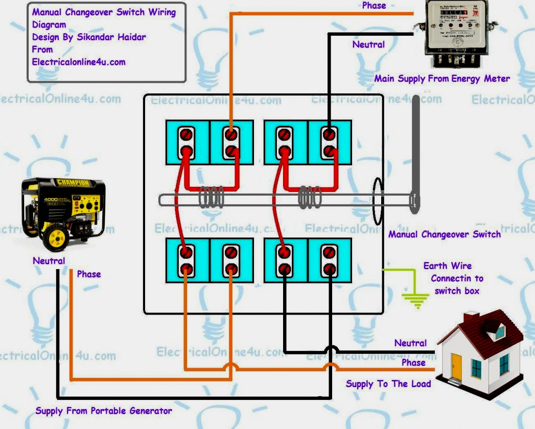
Alright, let's dive into manual transfer switch wiring diagrams. You might be looking at one of these for a few reasons: perhaps you're wiring a generator to your home's electrical system, diagnosing a fault, or simply trying to understand how your existing setup works. Whatever the reason, having a solid grasp of the wiring diagram is crucial. It's the roadmap to a safe and functional system, and misunderstanding it can lead to costly mistakes or, worse, serious injury.
Purpose of a Manual Transfer Switch Wiring Diagram
The wiring diagram is the central document for understanding, installing, and troubleshooting a manual transfer switch. Instead of just seeing a bunch of wires connected to terminals, it provides a structured, symbolic representation of the entire electrical circuit. This clarity is vital for:
- Installation: Following the diagram ensures you connect the wires correctly, avoiding shorts, open circuits, and potential fire hazards.
- Troubleshooting: When something goes wrong (power isn't transferring, circuits are tripping), the diagram helps you pinpoint the source of the problem. You can trace the circuit flow and identify potential failure points.
- Modification: If you need to modify the system (e.g., adding a new circuit or upgrading the switch), the diagram helps you plan the changes safely and effectively.
- Understanding System Operation: Even if you're not actively working on the system, the diagram provides a deeper understanding of how it functions, giving you more confidence in its reliability.
Key Specs and Main Parts Represented in the Diagram
Before we dig into the symbols, let's identify the key components you'll typically see in a manual transfer switch wiring diagram:
- The Manual Transfer Switch (MTS): This is the heart of the system. It's a multi-pole switch that allows you to select either the utility power source or the generator as the power source for your designated circuits. Typically, these switches have positions for "Utility," "Off," and "Generator."
- Utility Power Input: This is where the main power from the electric company enters the system. It's often represented by a connection to the main breaker panel.
- Generator Power Input: This is where the power from your generator enters the system. Important: The generator should be properly sized to handle the load of the circuits you're connecting.
- Load Panel/Subpanel: This is the panel that distributes power to the specific circuits you want to power with the generator. It's typically a subpanel isolated from the main service panel.
- Circuit Breakers: These protect individual circuits from overloads and short circuits. They are critical safety components.
- Neutral Bus Bar: This is the common connection point for all neutral wires.
- Ground Bus Bar: This is the common connection point for all grounding wires, providing a path for fault currents to safely return to the source.
- Wiring (Conductors): The wires themselves, carrying the electrical current between components.
Key specs you might find noted on the diagram (or accompanying documentation) include:
- Voltage Rating: The maximum voltage the system is designed to handle (e.g., 120/240V for residential applications).
- Current Rating: The maximum current the system can safely handle (e.g., 30A, 60A, 100A). This is usually determined by the transfer switch and circuit breaker ratings.
- Wire Gauge: The size of the wires used in the system (e.g., 12 AWG, 10 AWG, 8 AWG). This is crucial for ensuring the wires can handle the current without overheating.
- NEMA Rating: If the transfer switch is installed outdoors, its NEMA (National Electrical Manufacturers Association) rating indicates its level of protection against environmental factors like rain and dust.
Decoding the Symbols: Lines, Colors, and Icons
Wiring diagrams use standardized symbols to represent electrical components and connections. Here’s a breakdown of the common symbols you'll encounter:
- Solid Lines: These represent conductors (wires) carrying electrical current.
- Dashed Lines: Sometimes used to represent control wiring or signal wiring that doesn't carry the main power load.
- Circles: Can represent various components depending on what is inside it, sometimes they show test points, or the like.
- Rectangles: Often represent larger components such as circuit breakers, switches, or even entire panels.
- Zigzag Lines: Typically represent resistors or other devices that impede current flow.
- Ground Symbol (Three Lines Descending): Indicates a connection to the earth grounding system.
- Neutral Symbol (Line with a Short Perpendicular Line): Indicates the neutral conductor.
Color Coding: Color coding is crucial for correctly identifying wires. While standards can vary slightly by region, here are common conventions:
- Black: Typically represents hot (live) wires carrying current from the power source.
- Red: Often used for a second hot wire in a 240V circuit.
- White: Represents the neutral wire, which carries current back to the source but should ideally be at or near ground potential.
- Green (or Bare Copper): Represents the grounding wire, providing a safety path for fault currents.
Icons: Specific icons may be used to represent the manual transfer switch, generator, and other components. Consult the diagram's legend or accompanying documentation for clarification.
How It Works: Tracing the Circuit
Understanding how a manual transfer switch works is key to interpreting the wiring diagram. The basic principle is to isolate the selected circuits from the utility grid when the generator is running. Here's a simplified explanation:
- Normal Operation (Utility Power): The transfer switch is in the "Utility" position. Power flows from the utility grid, through the transfer switch, and into the designated load panel/subpanel, powering the connected circuits.
- Power Outage (Switch to Generator): When the utility power fails, you manually switch the transfer switch to the "Off" position. This completely disconnects the load panel from the utility grid.
- Generator Power: You start your generator. Once it's running and producing stable power, you switch the transfer switch to the "Generator" position. Power now flows from the generator, through the transfer switch, and into the load panel, powering the selected circuits.
- Returning to Utility Power: When the utility power is restored, you switch the transfer switch back to the "Off" position, let the generator cool down, and then switch to "Utility."
The wiring diagram will clearly show how the wires from each power source (utility and generator) connect to the transfer switch, and how the switch directs the power to the load panel based on its position. The diagram also details the necessary grounding and neutral connections to ensure proper operation and safety.
Real-World Use: Basic Troubleshooting Tips
Armed with the wiring diagram, you can troubleshoot common problems. Here are a few examples:
- No Power to Load Panel (Generator Position):
- Check the generator output voltage.
- Verify the generator circuit breaker is not tripped.
- Inspect the wiring connections at the generator and transfer switch for loose or corroded connections.
- Use the wiring diagram to trace the circuit from the generator to the load panel, looking for any breaks or interruptions.
- Circuit Breaker Tripping:
- Reduce the load on the circuit by turning off some appliances.
- Check for short circuits in the wiring or connected appliances.
- Verify that the circuit breaker is properly sized for the load.
- Consult the wiring diagram to ensure the circuit is wired correctly.
- Generator Not Supplying Power After Switching:
- Check that the generator is running and producing power.
- Check the breakers on the generator itself.
- Inspect the transfer switch for proper functionality. Use a multimeter to check for voltage at the transfer switch input terminals when the generator is running.
Safety: Handling Risky Components
Working with electrical systems is inherently dangerous. Here are critical safety precautions:
- Always Disconnect Power: Before working on any part of the electrical system, completely disconnect the power. Turn off the main breaker and the generator. Double-check with a voltage tester to ensure the circuits are de-energized.
- Wear Appropriate PPE: Use insulated tools, wear safety glasses, and consider wearing insulated gloves.
- Never Work Alone: Have someone nearby who can assist in case of an emergency.
- Understand the Hazards: Be aware of the risks of electrical shock and arc flash.
- If You're Unsure, Call a Professional: Don't hesitate to consult a qualified electrician if you're not comfortable working on the electrical system. Working with electricity is nothing to be taken lightly.
- Grounding is CRUCIAL: Improper grounding can create a serious shock hazard. Always ensure that the grounding system is properly connected and functioning.
High-voltage components within the transfer switch and generator can be extremely dangerous even when the system is seemingly off. Capacitors can store a charge, and residual voltage can remain in the wiring. Be extra cautious when working near these components.
This article provides a foundational understanding of manual transfer switch wiring diagrams. Always refer to the specific diagram for your system and follow all applicable electrical codes and safety regulations. We have a detailed wiring diagram file available for download, which can be a valuable resource as you work with these systems. Remember, safety first!