
Manual Transmission Components Diagram
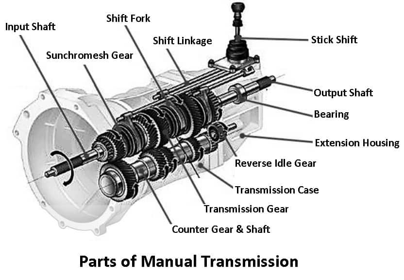
Understanding the inner workings of your manual transmission is crucial for anyone looking to perform maintenance, repairs, or even modifications. A comprehensive manual transmission components diagram is your roadmap to this intricate system. It's not just a picture; it's a key that unlocks a deeper understanding of how your car converts engine power into motion. This article will guide you through the anatomy of a manual transmission diagram, explaining the components, their functions, and how to use the diagram for practical troubleshooting.
Why a Manual Transmission Diagram Matters
Having access to a detailed manual transmission components diagram is invaluable for several reasons:
- Repairs and Maintenance: Diagnosing issues such as difficulty shifting, gear slippage, or unusual noises becomes significantly easier when you can visually trace the flow of power through the transmission. The diagram helps you identify the potential culprits.
- Learning and Understanding: For the aspiring mechanic or car enthusiast, a diagram offers a structured way to learn about the different components and their relationships within the transmission system.
- Modifications and Upgrades: Planning performance upgrades, like installing a short-throw shifter or stronger clutch, requires a solid understanding of the existing system. The diagram reveals potential compatibility issues or areas that need reinforcement.
- Sourcing Parts: When ordering replacement parts, the diagram allows you to precisely identify the component you need, minimizing the risk of ordering the wrong part. Many diagrams include part numbers directly.
Key Specs and Main Parts
A typical manual transmission diagram will highlight the following key components:
Essential Internal Components
- Input Shaft: This shaft receives power directly from the engine, typically through the clutch. It's the entry point of engine torque into the transmission.
- Output Shaft: This shaft delivers power to the driveshaft, which then transfers it to the wheels. It's the exit point of torque from the transmission.
- Gears (Spur Gears/Helical Gears): These are the heart of the transmission. Different gear ratios provide varying levels of torque and speed. Spur gears are simpler, but noisier; helical gears are stronger and quieter but generate axial thrust forces that must be managed with bearings.
- Synchronizers (Synchros): These ingenious devices match the speeds of the gears being engaged, preventing grinding and ensuring smooth shifts. A worn synchro is a common cause of shifting problems. They consist of a synchronizer ring (made of brass or a friction material), a hub, and sliders.
- Shift Forks: These forks move the synchronizers along the mainshaft to engage the desired gear. They are actuated by the shift linkage.
- Shift Rails: The rods that the shift forks ride on. They dictate the movement path of the forks.
- Countershaft (Lay Shaft): This shaft supports a set of gears that mesh with the input and output shaft gears, providing different gear ratios.
- Bearings: Bearings support the shafts and reduce friction, enabling smooth rotation. These can be ball bearings, roller bearings, or tapered roller bearings depending on the loads and speeds involved.
- Reverse Idler Gear: This gear reverses the direction of rotation of the output shaft, allowing the vehicle to move in reverse.
External Components
- Transmission Case: The housing that encloses all the internal components, protecting them from the elements and providing structural support.
- Shift Linkage: The system of rods and levers that connects the gear shift lever in the cabin to the shift forks within the transmission. Poorly adjusted shift linkage can cause shifting difficulties.
- Clutch Release Mechanism (Fork, Throwout Bearing, Clutch Master Cylinder/Slave Cylinder): Although technically not part of the transmission itself, the clutch release mechanism is crucial for disengaging the engine from the transmission during shifting.
- Fill Plug/Drain Plug: These plugs allow you to fill and drain the transmission fluid.
- Vent: Allows the transmission to "breathe", preventing pressure buildup from heat.
Understanding Diagram Symbols
Manual transmission diagrams use a variety of symbols to represent different components and connections. Common symbols include:
- Solid Lines: Typically represent shafts, shift rails, or other solid components. The thickness of the line might indicate the size or strength of the component.
- Dashed Lines: Often indicate the path of fluid flow (transmission oil) or control lines (e.g., vacuum lines in some older transmissions).
- Arrows: Indicate the direction of force or motion (e.g., the direction of rotation of a gear).
- Color Coding: Some diagrams use color coding to distinguish between different systems or materials. For example, one color might represent the input shaft, another the output shaft, and a third the shift linkage.
- Icons: Small icons may be used to represent specific components, such as bearings (often depicted as circles with smaller circles inside) or seals (often depicted as a ring with a hatched area).
- Labels and Annotations: Diagrams are typically accompanied by labels and annotations that identify each component and provide additional information about its function or specifications.
How It Works: The Big Picture
The basic principle is simple: the engine provides rotational force to the input shaft. This shaft turns gears inside the transmission. By selecting different gear ratios, the driver can trade off between torque and speed. Here’s a simplified breakdown:
- Power Input: The engine's power is transferred to the transmission via the input shaft. The clutch, controlled by the driver, allows this connection to be temporarily disengaged for shifting.
- Gear Selection: The driver selects a gear using the shift lever. This action moves the shift linkage, which in turn moves the shift forks inside the transmission.
- Synchronizer Engagement: The shift forks push the synchronizers against the gears on the output shaft. The synchronizers match the speed of the selected gear to the speed of the output shaft, preventing grinding.
- Power Output: Once the synchronizer has engaged, the selected gear is locked to the output shaft, and power is transferred to the driveshaft and ultimately to the wheels.
Real-World Use: Basic Troubleshooting
Let's say you're experiencing difficulty shifting into second gear. Using the diagram, you can trace the path of power and identify potential problem areas:
- Shift Linkage: Is the linkage properly adjusted? A loose or misaligned linkage can prevent the shift fork from fully engaging the synchronizer.
- Second Gear Synchronizer: Is the synchronizer worn? If the synchronizer isn't properly matching the speeds of the gear, it will be difficult to shift smoothly.
- Second Gear: Are the gear teeth damaged or worn? This could cause the gear to slip or grind.
- Shift Fork: Is the shift fork bent or worn? This could prevent it from properly engaging the synchronizer.
By visually inspecting these components (after disassembly, of course) and comparing them to the diagram, you can often pinpoint the root cause of the problem.
Safety Considerations
Working on a manual transmission involves potential hazards. Always take the following precautions:
- Disconnect the Battery: Prevent accidental electrical shorts.
- Support the Vehicle Properly: Use jack stands on a level surface. Never rely solely on a jack.
- Wear Safety Glasses: Protect your eyes from flying debris and chemicals.
- Use Gloves: Protect your hands from sharp edges and potentially harmful fluids. Transmission fluid can be carcinogenic.
- Be Mindful of Spring Pressure: Some internal components, such as shift rails and detents, are held in place by springs. Disassembling these components without proper tools can result in parts flying out with considerable force.
- Dispose of Fluids Properly: Do not pour used transmission fluid down the drain. Take it to a recycling center.
Special Note: The clutch is a high-friction device. Brake cleaner used to clean clutch components can become extremely toxic if ignited. Do not smoke or use open flame while working on clutch components. Ensure proper ventilation when using any cleaning solvents.
We have a detailed manual transmission components diagram available for download. It provides an exploded view and detailed information to assist you with your repair, maintenance, or modification projects.