Marquis Engine Diagram Mercury Grand Marquis Parts Diagram
Understanding your Mercury Grand Marquis, especially its engine, is crucial for effective maintenance, troubleshooting, and even performance modifications. A detailed Marquis engine diagram, and specifically a parts diagram, is your roadmap to navigating the complex inner workings of your vehicle. This article will break down the diagram, explain its key components, and guide you on how to use it for both learning and practical applications.
Purpose of the Engine and Parts Diagram
Why bother with an engine diagram? Simple: it's your go-to resource for nearly everything related to your engine. Here's why it matters:
- Repair and Maintenance: Identifying parts for replacement, understanding their location, and ensuring proper installation.
- Troubleshooting: Tracing problems by following fuel lines, vacuum hoses, or electrical circuits.
- Modifications: Planning performance upgrades by understanding existing system limitations and potential interactions.
- Learning: Gaining a deeper understanding of how your engine operates and the relationship between different components.
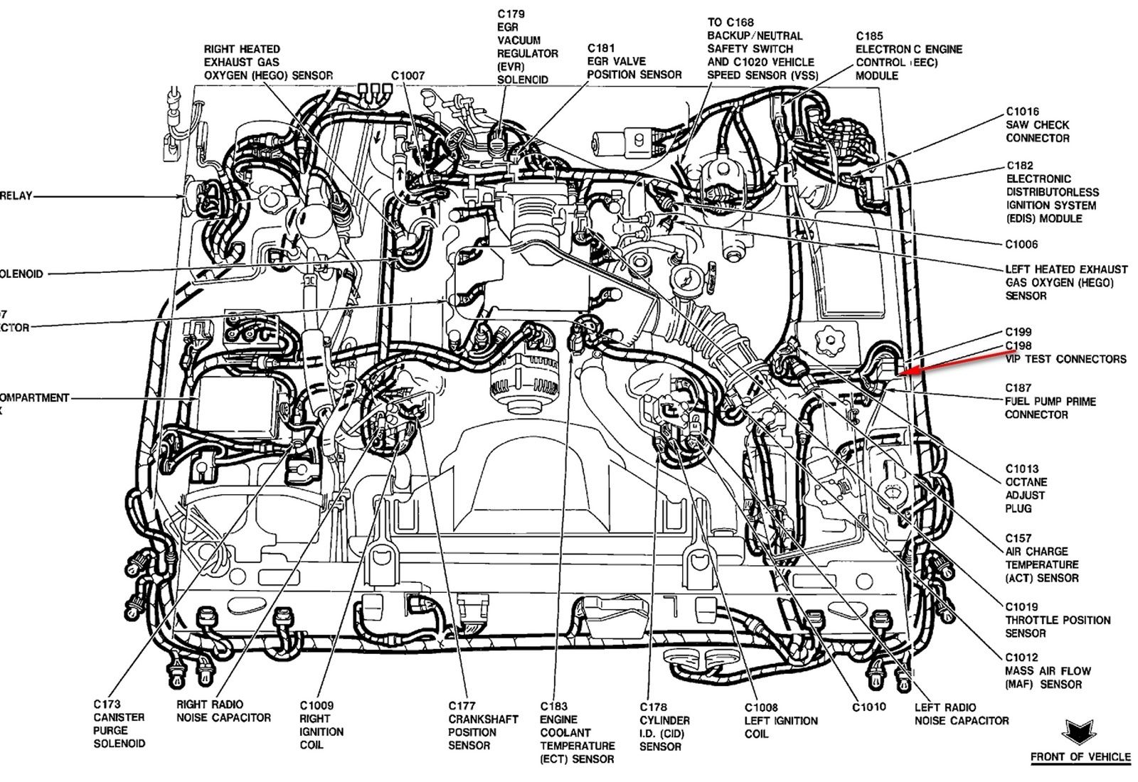
Key Specs and Main Parts of the Grand Marquis Engine (4.6L Modular V8)
The Mercury Grand Marquis primarily used the 4.6L Modular V8 engine. Here's a breakdown of key components you'll find in the diagram:
Main Engine Block
The heart of the engine, housing the cylinders. Its material is typically cast iron or aluminum in later models. The diagram will show the block's mounting points and connections for other systems.
Cylinder Heads
Located on top of the engine block, containing the valves, valve springs, and camshaft(s). The 4.6L V8 is typically an overhead cam (OHC) or single overhead cam (SOHC) design. The diagram will illustrate the valve train layout and the location of the camshaft position sensor (CMP).
Pistons and Connecting Rods
These convert the combustion pressure into mechanical motion. The diagram shows their relationship to the crankshaft and how they connect to the connecting rod bearings.
Crankshaft
This rotating shaft converts the reciprocating motion of the pistons into rotational motion, which drives the transmission. The diagram will detail the crankshaft's location, its bearings, and the connecting point for the harmonic balancer/damper.
Intake Manifold
Distributes air to the cylinders. The diagram illustrates its ports, vacuum connections, and the location of the throttle body.
Exhaust Manifold/Headers
Collects exhaust gases from the cylinders. The diagram will show its connection to the catalytic converter and the location of the oxygen (O2) sensors.
Fuel Injection System
Delivers fuel to the cylinders. The diagram will show the fuel injectors, fuel rails, fuel pressure regulator, and the connection to the fuel pump. The diagram will also show the location of the Fuel Injector Control Module.
Ignition System
Provides the spark to ignite the air-fuel mixture. The 4.6L V8 used a coil-on-plug (COP) ignition system. The diagram will show the individual ignition coils, spark plugs, and the connection to the PCM (Powertrain Control Module).
Cooling System
Maintains engine temperature. The diagram will show the water pump, thermostat housing, radiator hoses, and the location of the coolant temperature sensor (CTS).
Lubrication System
Provides oil to lubricate the engine components. The diagram will show the oil pump, oil filter, oil pan, and the oil pressure sensor.
Understanding Symbols on the Diagram
Engine diagrams use standardized symbols to represent different components and connections. Here's a guide:
- Solid Lines: Typically represent fluid lines (fuel, coolant, oil).
- Dashed Lines: Usually indicate vacuum lines or electrical wiring.
- Dotted Lines: Can represent hidden components or internal pathways within a part.
- Color Coding: Diagrams sometimes use color to distinguish different systems (e.g., red for fuel, blue for coolant, green for vacuum).
- Symbols for Components: Each part has a unique symbol. A square might represent a sensor, a circle with an 'X' might represent a plug, and so on. Refer to the diagram's legend for a complete list.
Always refer to the specific diagram's key or legend for accurate interpretation.
How the Engine Works (Simplified)
The 4.6L Modular V8 operates on the four-stroke principle:
- Intake: The piston moves down, drawing air and fuel into the cylinder.
- Compression: The piston moves up, compressing the air-fuel mixture.
- Combustion: The spark plug ignites the compressed mixture, creating an explosion that forces the piston down.
- Exhaust: The piston moves up, pushing the exhaust gases out of the cylinder.
The engine diagram will illustrate how each system contributes to this process, showing the flow of air, fuel, and exhaust, as well as the timing of ignition.
Real-World Use: Basic Troubleshooting Tips
Here's how to use the engine diagram for basic troubleshooting:
- Engine Misfire: If you suspect a misfire, the diagram can help you locate the ignition coils and spark plugs for inspection. You can trace the wiring back to the PCM to check for wiring issues.
- Coolant Leak: The diagram will show the coolant hoses, water pump, and thermostat housing. Inspect these areas for leaks based on the diagram.
- Vacuum Leak: Vacuum leaks can cause rough idling. Use the diagram to trace the vacuum lines and identify potential sources of leaks. A common culprit is the PCV valve and its hose.
- Fuel Delivery Problems: If the engine is not getting fuel, the diagram will help you locate the fuel pump, fuel filter, fuel injectors, and fuel pressure regulator for testing.
Safety Considerations
Working on your engine involves inherent risks. Here are a few things to keep in mind:
- Fuel System: The fuel system is highly flammable. Disconnect the battery before working on it and avoid sparks or open flames. Depressurize the fuel system before disconnecting any fuel lines.
- Electrical System: Disconnect the battery to prevent electrical shocks. Be careful when working near the ignition system, as it can generate high voltage.
- Cooling System: The coolant can be very hot. Allow the engine to cool down before working on the cooling system.
- Exhaust System: The exhaust system can be extremely hot. Allow it to cool down before working on it.
- Moving Parts: Always disconnect the battery and ensure the vehicle is in park (or neutral for manual transmissions) before working near any moving parts.
Always consult a repair manual and follow proper safety procedures when working on your vehicle.
By understanding the engine and parts diagram, you can confidently perform basic maintenance, troubleshoot common problems, and even plan performance upgrades. Remember to always prioritize safety and consult a qualified mechanic if you're unsure about any repair.
We have the file available for you. Please contact us to download the detailed Marquis engine and parts diagram for your Mercury Grand Marquis.