Mass Air Flow Sensor Wiring Diagram
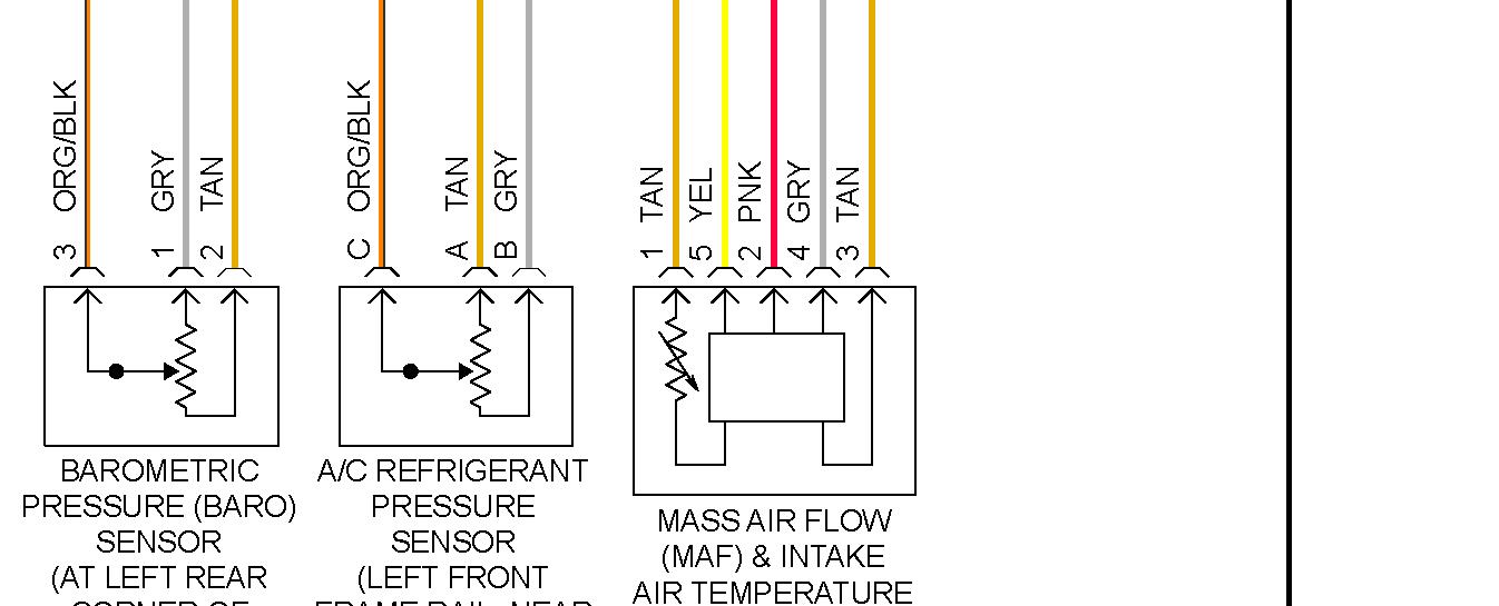
Understanding your car's Mass Air Flow (MAF) sensor wiring diagram is crucial for diagnosing engine performance issues, performing upgrades, or even just expanding your automotive knowledge. This isn't just some academic exercise; it's a practical skill that can save you time and money on repairs. Whether you're troubleshooting a persistent check engine light, planning a forced induction modification, or simply curious about how your engine management system works, knowing how to read and interpret a MAF sensor wiring diagram is a valuable asset.
Purpose: Why Bother with the Wiring Diagram?
The MAF sensor wiring diagram is your roadmap to understanding how the MAF sensor interacts with the Engine Control Unit (ECU), the brain of your car. It provides a detailed visual representation of the sensor's electrical connections, showing which wires go where, their functions, and how they're connected to other components within the engine management system. This knowledge is essential for several reasons:
- Troubleshooting: Diagnosing a faulty MAF sensor isn't always about replacing the sensor itself. Damaged wiring, corroded connectors, or shorts in the circuit can all mimic the symptoms of a bad sensor. The wiring diagram allows you to systematically check the integrity of the entire circuit, pinpointing the source of the problem.
- Repairing Damage: Accidents, rodent damage, or general wear and tear can damage the MAF sensor wiring. The diagram helps you identify the correct wires to repair or replace, ensuring proper connections and preventing further damage.
- Modifications and Upgrades: If you're planning engine modifications, such as installing a turbocharger or supercharger, you might need to upgrade your MAF sensor. The wiring diagram is essential for correctly integrating the new sensor into your existing system.
- Learning and Understanding: Even if you're not planning any immediate repairs, studying the wiring diagram can give you a deeper understanding of how your engine management system works. This knowledge can be invaluable for future troubleshooting or even just appreciating the complexity of modern automotive technology.
Key Specs and Main Parts
Before diving into the diagram itself, let's review the key components and their roles:
- MAF Sensor: The core component. It measures the mass of air entering the engine. Common types include hot-wire and hot-film sensors.
- ECU (Engine Control Unit): The brain of the operation. It receives the MAF sensor's signal and uses it to calculate the correct amount of fuel to inject into the engine.
- Power Supply (Typically 12V): Provides the necessary voltage to power the MAF sensor's internal circuitry.
- Ground: Provides a return path for the electrical current. A good ground connection is crucial for accurate sensor readings.
- Signal Wire: Carries the analog or digital signal from the MAF sensor to the ECU, representing the measured airflow.
- Temperature Sensor (IAT - Intake Air Temperature): Often integrated into the MAF sensor, this sensor measures the temperature of the incoming air, which is used to correct the airflow reading for density variations.
Symbols: Decoding the Wiring Diagram
Wiring diagrams use a standardized set of symbols to represent electrical components and connections. Understanding these symbols is key to interpreting the diagram correctly:
- Lines: Represent wires. Solid lines indicate a direct connection, while dashed lines might indicate a shielded wire or a connection through a connector. Wire thickness can sometimes indicate the wire gauge (thicker lines usually denote thicker wires, capable of carrying more current).
- Colors: Each wire is typically identified by a color code (e.g., RED, BLU, GRN/YEL). This is crucial for identifying the correct wires when troubleshooting or making repairs. You'll find a color code legend on the diagram.
- Connectors: Represented by squares or rectangles. These show where wires are connected to each other or to components. Connector pin numbers are often indicated to specify which wire goes to which pin.
- Ground Symbols: Various symbols represent ground connections. Common symbols include a series of descending horizontal lines or a stylized "T" shape.
- Resistors: Zigzag lines represent resistors, which limit current flow.
- Capacitors: Two parallel lines represent capacitors, which store electrical energy.
- Diodes: A triangle pointing towards a line represents a diode, which allows current to flow in only one direction.
- Sensors: Various symbols depict different types of sensors. The MAF sensor symbol is often a rectangle with an arrow indicating airflow.
How It Works: From Airflow to Engine Management
The MAF sensor's operation is surprisingly elegant. Here's a simplified explanation:
- Air enters the engine through the air intake.
- The MAF sensor, located in the intake tract, measures the mass of this air. In a hot-wire MAF sensor, a heated wire is exposed to the airflow. The more air that flows past the wire, the more it cools down. The sensor's electronics maintain a constant wire temperature by increasing the current flowing through it. The amount of current required to maintain the temperature is directly proportional to the mass of air flowing past the wire.
- The sensor converts this airflow measurement into an electrical signal, typically a voltage or frequency signal.
- The signal is sent to the ECU via the signal wire.
- The ECU uses this information, along with other sensor data (e.g., engine speed, throttle position, coolant temperature), to calculate the optimal amount of fuel to inject into the cylinders.
- By precisely controlling the air-fuel mixture, the ECU ensures efficient combustion, optimal performance, and minimal emissions.
Real-World Use: Basic Troubleshooting Tips
Here are a few common troubleshooting scenarios and how the wiring diagram can help:
- P0101, P0102, P0103 Codes: These codes often indicate a problem with the MAF sensor circuit. Use the wiring diagram to check for continuity (unbroken circuits) in each wire, test the voltage at the power supply wire, and verify the ground connection.
- Erratic Idle or Stalling: A faulty MAF sensor signal can cause the engine to run poorly. Use a multimeter to check the signal wire's voltage or frequency while the engine is running. Compare the readings to the manufacturer's specifications.
- Poor Fuel Economy: An inaccurate MAF sensor reading can lead to over-fueling, resulting in reduced fuel economy. Check the wiring for any signs of damage or corrosion that might be affecting the signal.
- Check for Shorts: If you suspect a short circuit, use the wiring diagram and a multimeter to check for continuity between the signal wire and ground. A short to ground can cause the ECU to receive incorrect readings.
Remember to consult your vehicle's specific repair manual for detailed troubleshooting procedures and diagnostic information. Generic code readers only provide a starting point; a proper diagnosis often requires using more sophisticated tools and techniques.
Safety: Handle with Care!
Working with automotive electrical systems can be dangerous. Here are a few important safety precautions:
- Disconnect the Battery: Always disconnect the negative battery terminal before working on any electrical components. This will prevent accidental shorts and electrical shocks.
- Use a Multimeter Correctly: Make sure you understand how to use a multimeter before attempting any electrical testing. Incorrect use can damage the multimeter or even cause injury.
- Be Careful with Wires: Avoid pulling or stressing wires. Damaged wires can cause shorts and other electrical problems.
- Airbag Systems: Be extremely careful when working near airbag systems. Accidental deployment of an airbag can cause serious injury. If you're unsure about working near airbags, consult a qualified technician. Specifically, note that the MAF sensor wiring often runs near airbag sensors, making careful handling even more crucial.
- Fuel Lines: Be mindful of fuel lines in the area. Damaging a fuel line can create a fire hazard.
The ECU itself is highly sensitive to voltage spikes and shorts. Incorrectly wiring the MAF sensor can damage the ECU, leading to costly repairs. If you're not comfortable working with electrical systems, it's best to consult a qualified mechanic.
This information provides a general overview of MAF sensor wiring diagrams. Consult your vehicle's specific service manual for detailed wiring schematics and troubleshooting procedures.
We have a sample MAF sensor wiring diagram file available for download. Analyzing it alongside this guide will greatly improve comprehension.