
Master Cylinder Brake Booster Diagram
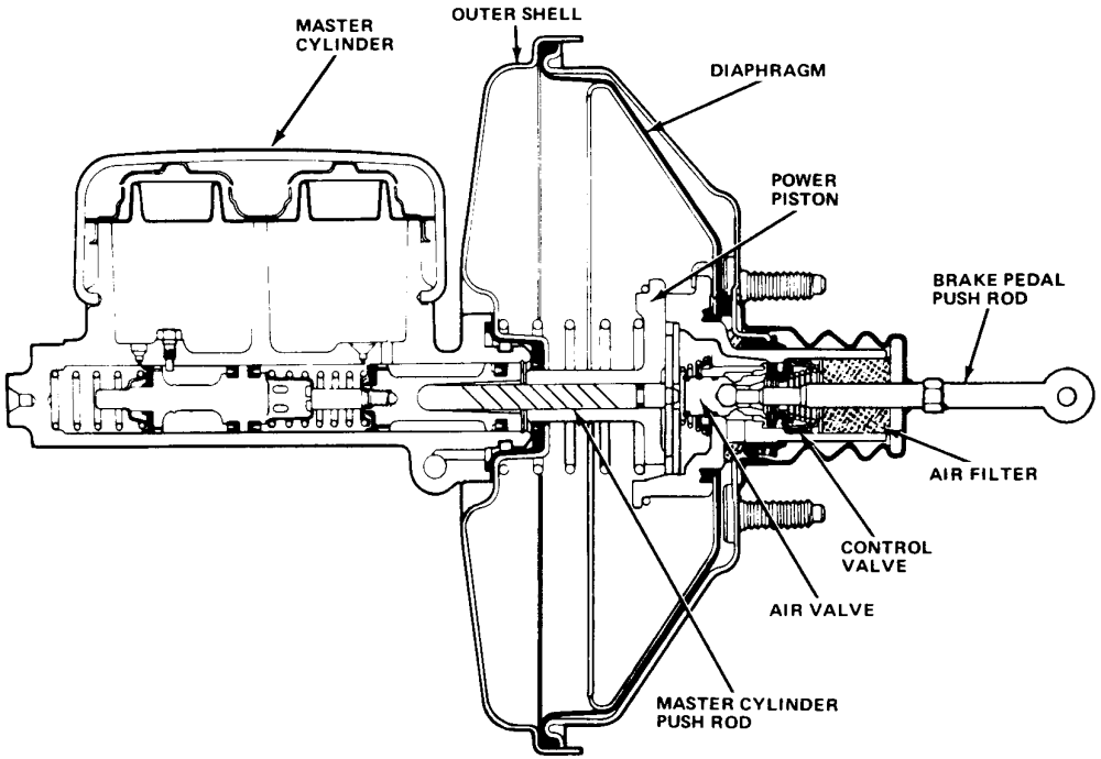
Understanding the interplay between the master cylinder and brake booster is crucial for anyone undertaking brake system repairs, upgrades, or even just trying to diagnose a puzzling brake issue. This article will serve as your guide to interpreting a master cylinder brake booster diagram, providing insights into its components, operation, and troubleshooting.
Why Bother with a Diagram?
A master cylinder brake booster diagram isn't just a pretty picture. It's a roadmap to understanding a critical system in your vehicle. Here's why you should care:
- Repair and Maintenance: Diagnosing brake problems can be challenging. A diagram helps you pinpoint the source of the issue, whether it's a leak in the master cylinder, a faulty booster, or a vacuum line problem.
- Upgrades and Modifications: Swapping out brake components, such as upgrading to a larger master cylinder or a more powerful booster, requires understanding the existing system's layout and connections.
- Learning and Education: For the aspiring DIY mechanic, a diagram provides a visual representation of how the brake system works, fostering a deeper understanding of automotive technology.
- Safety: Brakes are arguably the most important safety system in your car. Understanding how they work allows you to identify potential problems before they become dangerous.
Key Specs and Main Parts
Before diving into the diagram itself, let's define the key components:
- Master Cylinder: The heart of the hydraulic brake system. It contains reservoirs of brake fluid and pistons that, when pushed by the brake pedal, force fluid through the brake lines to the calipers or wheel cylinders at each wheel.
- Brake Booster (Power Booster): A vacuum-assisted device that amplifies the force applied to the brake pedal, making it easier to stop the vehicle. It uses engine vacuum to assist the driver.
- Vacuum Line: Connects the brake booster to the engine's intake manifold, providing the vacuum source.
- Pushrod: Connects the brake pedal to the master cylinder piston. In boosted systems, there is also a pushrod connecting the booster to the master cylinder.
- Reservoir: Holds the brake fluid that feeds the master cylinder.
- Brake Lines: Metal or rubber lines that carry brake fluid to the wheels.
- Calipers/Wheel Cylinders: Convert hydraulic pressure into mechanical force to apply the brakes at the wheels.
Key Specs to Consider:
- Master Cylinder Bore Size: Affects the amount of fluid displaced and the pedal feel. Larger bore = less pedal travel, more force required.
- Booster Diameter: Dictates the amount of boost provided. Larger diameter = more boost.
- Vacuum Requirements: Boosters need a specific vacuum level to operate correctly.
- Brake Fluid Type: Using the wrong fluid can damage seals and components (DOT 3, DOT 4, DOT 5.1 are common)
Symbols and Conventions in a Brake Diagram
Understanding the symbols used in a brake diagram is essential for accurate interpretation. While specific symbols may vary slightly between manufacturers, some common conventions apply:
- Solid Lines: Typically represent hydraulic lines carrying brake fluid under pressure.
- Dashed Lines: Usually indicate vacuum lines or control lines.
- Color Coding: May be used to differentiate between different circuits or fluid types. Check the diagram's legend.
- Arrows: Show the direction of fluid or vacuum flow.
- Reservoirs: Depicted as containers with a level indicator.
- Pistons: Represented as cylindrical shapes within the master cylinder and booster.
- Springs: Illustrate the presence of return springs within the system.
- Valves: Show the location and type of valves that regulate fluid flow or vacuum.
Important Note: Always refer to the specific diagram's legend or key for accurate interpretation of symbols and color codes.
How It Works: The Brake Booster Master Cylinder System
Let's break down the operational sequence:
- Brake Pedal Application: When the driver presses the brake pedal, the pushrod applies force to the master cylinder piston(s).
- Master Cylinder Operation: The piston(s) inside the master cylinder displace brake fluid from the reservoir and into the brake lines.
- Brake Booster Assistance: Simultaneously, the brake pedal movement triggers the brake booster. Engine vacuum, applied through the vacuum line, creates a pressure differential within the booster. This pressure differential amplifies the force applied to the master cylinder piston(s). This is the "boost" you feel.
- Hydraulic Pressure Transfer: The pressurized brake fluid travels through the brake lines to the calipers (for disc brakes) or wheel cylinders (for drum brakes).
- Braking Action: The calipers or wheel cylinders convert the hydraulic pressure into mechanical force, pressing the brake pads against the rotors (disc brakes) or the brake shoes against the drums (drum brakes), slowing or stopping the vehicle.
- Release: When the brake pedal is released, return springs retract the pistons in the master cylinder and calipers/wheel cylinders, allowing the brake pads/shoes to move away from the rotors/drums.
Real-World Use: Basic Troubleshooting Tips
A diagram can be invaluable for troubleshooting. Here are a few common issues and how a diagram can help:
- Spongy Brake Pedal: Could indicate air in the brake lines. The diagram helps you trace the brake lines to identify potential leak points.
- Hard Brake Pedal (Little to No Boost): Points to a problem with the brake booster or its vacuum supply. Check the vacuum line connections, the booster itself, and the check valve (if equipped). A diagram will show you the location of the vacuum line and check valve.
- Brake Fluid Leaks: Identify the source of the leak by visually tracing the brake lines and components. The diagram helps you understand where the connections are and what components might be leaking.
- Brakes Not Releasing: Could be a problem with the master cylinder not returning properly. The diagram shows the return spring location and piston arrangement.
- Pulling to One Side During Braking: Often indicates a problem with a caliper or wheel cylinder on one side of the vehicle. The diagram helps you identify the affected circuit.
Before doing any work on your brake system, disconnect the negative battery terminal.
Safety Considerations
The brake system is a critical safety component. Exercise extreme caution when working on it. Here are some key safety points:
- Brake Fluid: Brake fluid is corrosive and can damage painted surfaces. Wear eye protection and gloves when handling it.
- High Pressure: The hydraulic system operates under high pressure. Relieve pressure before disconnecting any lines.
- Proper Bleeding: After opening the system, it's crucial to bleed the brakes to remove air. Air in the lines will significantly reduce braking performance.
- Vacuum Lines: Be careful when handling vacuum lines near the engine, as they can be hot.
- Contaminated Fluid: Never allow contaminants to enter the brake system. Use clean tools and containers.
- Booster Check Valve: The check valve in the vacuum line to the booster is a critical safety component. Ensure it's functioning correctly to maintain boost in case of engine stall. A faulty check valve can lead to brake failure.
Disclaimer: Brake work should only be performed by qualified individuals. If you are not comfortable working on your brakes, seek professional assistance.
With a solid understanding of your vehicle's brake system, you'll be well-equipped to tackle repairs, upgrades, and maintenance with confidence. Remember that this explanation is just a starting point. Always consult your vehicle's service manual for specific information and procedures.
We have a high-resolution version of a generic master cylinder brake booster diagram available for download. Understanding your specific vehicle's diagram is essential, but this general diagram will provide a helpful visual aid.