Mercedes Sl500 1997 Front Control Arms Diagram
The 1997 Mercedes-Benz SL500 is a classic roadster known for its blend of luxury and performance. Understanding its suspension system, particularly the front control arms, is crucial for maintaining its ride quality and handling. This article delves into the front control arm diagram, explaining its components, function, and practical applications for DIY mechanics.
Purpose of the Front Control Arm Diagram
Why bother with a diagram? Well, several reasons. First and foremost, it's indispensable for accurate repairs. When dealing with complex systems like the front suspension, a diagram ensures you identify the correct parts, torque them to spec, and assemble everything in the right sequence. Secondly, it’s a great learning tool. If you're interested in understanding how your SL500's suspension works, studying the diagram provides valuable insights. Finally, it aids in diagnosing problems. By knowing the function of each component, you can better pinpoint the source of issues like clunking noises, uneven tire wear, or poor handling.
Key Specs and Main Parts of the Front Control Arm Assembly
The SL500 (R129 chassis) utilizes a double-wishbone (or double A-arm) front suspension. This design offers excellent handling characteristics by controlling camber and caster angles throughout the suspension travel. Let's break down the key components:
- Upper Control Arm: Also known as the upper A-arm. Connects the steering knuckle (the hub that holds the wheel bearings and brake components) to the vehicle's frame. It primarily controls the upper part of the wheel's movement.
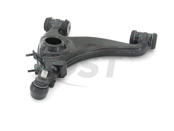
- Lower Control Arm: Also known as the lower A-arm. Similar to the upper arm but usually larger and more robust, as it bears more load. Connects the steering knuckle to the frame and controls the lower part of the wheel's movement.
- Ball Joints: These are spherical bearings that allow the control arms to move freely while still maintaining a strong connection to the steering knuckle. Critical for smooth steering and suspension articulation.
- Control Arm Bushings: These are rubber (or sometimes polyurethane) bushings that are pressed into the control arms where they attach to the vehicle's frame. They absorb vibrations and allow for limited movement, preventing noise and harshness from being transmitted to the cabin. Deteriorated bushings are a common cause of suspension problems.
- Sway Bar (Anti-Roll Bar) Link: Connects the sway bar to the control arm or strut assembly. Helps to reduce body roll during cornering.
- Shock Absorber (Strut): Controls the movement of the suspension by dampening oscillations. The shock absorber is typically mounted between the lower control arm and the vehicle's frame.
- Coil Spring: Provides the primary suspension support and absorbs bumps in the road. In the SL500, the spring is separate from the shock absorber.
Typical specs to be aware of include torque specifications for all bolts and fasteners (critical for safety and proper function), control arm lengths (though less relevant for DIY replacement, it’s important for understanding suspension geometry), and bushing durometer (hardness) if you’re considering aftermarket bushing upgrades.
Understanding Diagram Symbols
Control arm diagrams, like most technical drawings, use a standardized set of symbols. Here's a general guide, but keep in mind that specific diagrams might have slight variations:
- Solid Lines: Typically represent physical components, such as the control arms themselves, the shock absorber, or the sway bar.
- Dashed Lines: Can indicate hidden components or lines of force/movement. They might also represent the centerline of a part.
- Arrows: Show the direction of movement or force. For example, an arrow might indicate the direction of travel of the suspension.
- Circles or Ovals: Often represent fasteners like bolts, nuts, and rivets. Pay attention to the numbers next to these circles, as they often correspond to a parts list or torque specification table.
- Cross-hatching: Indicates a cutaway view of a component, revealing its internal structure.
- Color Coding: While not always present, color coding can highlight different materials (e.g., steel, aluminum, rubber) or different systems within the suspension.
Important Note: Always refer to the legend or key on the diagram itself to understand the specific meaning of each symbol used.Ignoring the legend can lead to misinterpretations and errors.
How the Front Control Arm Suspension Works
The double-wishbone suspension provides superior handling compared to simpler designs. As the wheel encounters a bump, the suspension compresses, causing the control arms to move upwards. The ball joints allow the wheel to pivot and maintain contact with the road. The shock absorber dampens the movement, preventing excessive bouncing. The coil spring provides the resistance needed to support the vehicle's weight and absorb impacts.
The key advantage of the double-wishbone design lies in its ability to control camber and caster angles. Camber is the angle of the wheel relative to vertical when viewed from the front. Caster is the angle of the steering axis relative to vertical when viewed from the side. By carefully designing the geometry of the control arms, engineers can minimize changes in these angles as the suspension travels, resulting in improved tire contact and handling.
Real-World Use: Basic Troubleshooting Tips
Here are some common problems associated with front control arms and how to troubleshoot them using the diagram as a reference:
- Clunking or Rattling Noises: Often caused by worn-out ball joints or control arm bushings. Inspect these components for play or damage. The diagram will help you locate each bushing and ball joint precisely.
- Uneven Tire Wear: Can result from misaligned suspension components, including bent control arms or worn ball joints. A visual inspection using the diagram to identify each part is the first step, followed by a professional alignment.
- Poor Handling: Can be caused by a variety of factors, including worn shock absorbers, loose ball joints, or damaged control arm bushings. The diagram will help you understand the relationship between these components and diagnose the problem.
- Steering Wander: Can indicate issues with ball joints, tie rod ends, or control arm bushings. Again, use the diagram to guide your inspection.
Pro Tip: When inspecting suspension components, use a pry bar to apply leverage and check for play in the ball joints and bushings. Any excessive movement indicates a worn part that needs replacement.
Safety Considerations
Working on suspension systems can be dangerous due to the high spring forces involved. Always take the following precautions:
- Use proper lifting equipment: Always use a sturdy jack and jack stands to support the vehicle. Never work under a vehicle supported only by a jack.
- Compress springs safely: If you need to remove the coil spring, use a spring compressor. Improper use of a spring compressor can result in serious injury.
- Loosen fasteners carefully: Suspension fasteners can be very tight and may require significant force to loosen. Use appropriate tools and techniques to avoid injury.
- Wear safety glasses: Protect your eyes from flying debris.
- Be aware of ABS/Brake lines: Take extra care when working around the brake lines and ABS sensors/wires. Accidental damage to these could create a serious safety risk when driving.
Warning: The coil spring stores a significant amount of energy. Releasing this energy suddenly can cause serious injury or death. If you are not comfortable working with coil springs, seek professional assistance.
After any suspension work, it's crucial to get a professional wheel alignment. This ensures proper handling and prevents premature tire wear.
We have the high-resolution diagram available for download, and you can use it for your repair, diagnosis, and maintenance of your 1997 Mercedes-Benz SL500 Front Control Arm.