Mercedes Sprinter Wiring Diagram Pdf
The Mercedes Sprinter, a workhorse for businesses and adventurers alike, is a complex machine. When tackling electrical repairs, upgrades, or even just trying to understand its inner workings, a reliable wiring diagram is indispensable. Think of it as the roadmap to your Sprinter's nervous system. This article will delve into the intricacies of a Mercedes Sprinter wiring diagram PDF, equipping you with the knowledge to navigate its complexities and confidently tackle electrical projects.
Purpose: Why You Need a Sprinter Wiring Diagram
A wiring diagram isn't just a pretty picture; it's a vital tool for various scenarios:
- Troubleshooting Electrical Issues: Diagnosing why your lights aren't working, your radio is dead, or your power windows are stuck.
- Performing Repairs: Accurately identifying and replacing faulty components without causing further damage.
- Installing Aftermarket Accessories: Safely and correctly wiring in accessories like auxiliary lighting, stereos, alarms, or camper van conversions.
- Understanding Vehicle Systems: Gaining a deeper understanding of how different systems in your Sprinter are interconnected.
- Preventing Costly Mistakes: Avoiding accidental shorts, blown fuses, or damage to sensitive electronic control units (ECUs).
Without a wiring diagram, you're essentially working blind, increasing the risk of damaging your vehicle and wasting time and money.
Key Specs and Main Parts of a Sprinter Wiring Diagram
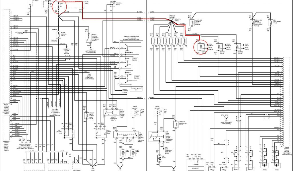
Sprinter wiring diagrams vary depending on the model year, engine type, and specific options installed. However, some key components and conventions are consistent:
- Vehicle Identification Number (VIN): The VIN is crucial. It allows you to pinpoint the exact wiring diagram corresponding to your specific Sprinter model and its factory-installed features. Make sure the diagram you're using matches your VIN.
- System Identification: Diagrams are typically organized by system, such as starting/charging, lighting, body electrical, engine management, ABS, etc.
- Component Identification: Each component (e.g., relay, sensor, switch, motor) is labeled with a unique identifier. This identifier is often referenced throughout the diagram.
- Wire Gauges and Colors: The diagram specifies the wire gauge (thickness) and color. The wire gauge is usually indicated by a number (e.g., 16 AWG, 14 AWG). Heavier gauge wires can handle more current. Color codes are crucial for correctly identifying wires in the harness.
- Ground Points: Clearly marked ground points (often indicated by a symbol resembling an upside-down Christmas tree) are essential for proper circuit operation. A faulty ground connection can cause a wide range of electrical problems.
- Connectors: Connectors are shown as rectangles or other shapes, often with a connector number and pin assignments.
- Fuses and Relays: Fuse locations and ratings are typically indicated. Relays are shown as symbols representing their internal switching mechanisms. Understanding fuse ratings is critical to preventing overloads and potential fires.
Decoding Sprinter Wiring Diagram Symbols
Understanding the symbols used in the diagram is key to interpreting the information it provides:
- Lines: Solid lines represent wires, while dashed lines may indicate shielding or connections to other systems. The thickness of the line doesn't necessarily indicate wire gauge.
- Colors: Wire colors are typically abbreviated using a standardized code (e.g., BR = Brown, BK = Black, RD = Red, BL = Blue, GN = Green, YE = Yellow, WH = White). Some diagrams use two- or three-letter codes.
- Component Symbols:
- Resistors: Represented by a zig-zag line.
- Capacitors: Represented by two parallel lines.
- Diodes: Represented by a triangle pointing to a vertical line.
- Switches: Represented by a line that can be open (off) or closed (on).
- Relays: Represented by a coil and a set of switch contacts.
- Grounds: Represented by a symbol resembling an upside-down Christmas tree or a series of decreasing horizontal lines.
- Connectors: Represented as rectangles or other geometric shapes, with pin numbers indicated.
- Abbreviations: Familiarize yourself with common automotive electrical abbreviations (e.g., ECU, PCM, ABS, SRS).
How It Works: Understanding Circuit Flow
A wiring diagram essentially illustrates the path of electrical current through a circuit. Current flows from the power source (usually the battery), through various components (switches, relays, loads), and back to ground. Understanding this flow is crucial for troubleshooting. For example, if a light isn't working, you would trace the circuit back from the light, checking for voltage at each point. If you find voltage at one point but not the next, there's a break in the circuit between those points (e.g., a broken wire, a faulty connector, or a blown fuse). Always start with the simplest checks first, such as examining fuses and connectors.
Real-World Use: Basic Troubleshooting Tips
Here are some practical tips for using a Sprinter wiring diagram for troubleshooting:
- Start with the Symptoms: Identify the specific problem and the affected system.
- Locate the Relevant Diagram: Use your VIN to find the correct wiring diagram for the affected system.
- Trace the Circuit: Follow the wiring diagram to trace the circuit from the power source to the affected component and back to ground.
- Use a Multimeter: A multimeter is essential for measuring voltage, current, and resistance. Use it to check for voltage at various points in the circuit and to test the continuity of wires and components.
- Check Fuses and Relays: Always check fuses and relays before moving on to more complex troubleshooting steps. Use the diagram to identify the correct fuse or relay for the affected circuit.
- Inspect Connectors: Look for corroded, loose, or damaged connectors. Clean and reseat connectors as needed.
- Isolate the Problem: Try to isolate the problem to a specific component or section of the wiring.
- Consult Online Forums and Repair Manuals: Online forums and repair manuals can provide valuable information and troubleshooting tips specific to your Sprinter model.
Safety First: Handle with Care
Working with electrical systems can be dangerous. Here are some crucial safety precautions:
- Disconnect the Battery: Always disconnect the negative battery terminal before working on any electrical system. This prevents accidental shorts and potential electrical shocks.
- Use Proper Tools: Use insulated tools designed for electrical work.
- Be Aware of High-Voltage Components: Certain components, such as the airbag system (SRS) and the fuel injection system, can store high voltages even after the battery is disconnected. Consult a qualified technician before working on these systems.
- Never Work Alone: It's always a good idea to have someone nearby in case of an emergency.
- Double-Check Your Work: Before reconnecting the battery, carefully double-check your work to ensure that all connections are secure and that there are no loose wires or potential shorts.
- If You're Unsure, Seek Professional Help: If you're not comfortable working on electrical systems, don't hesitate to seek professional help from a qualified mechanic.
Electrical systems in vehicles can be complex and hazardous. Always prioritize safety and take the necessary precautions to avoid injury or damage to your vehicle.
We have access to a variety of Mercedes Sprinter wiring diagrams in PDF format, covering different model years and configurations. Knowing the VIN of your Sprinter is essential to selecting the correct diagram.