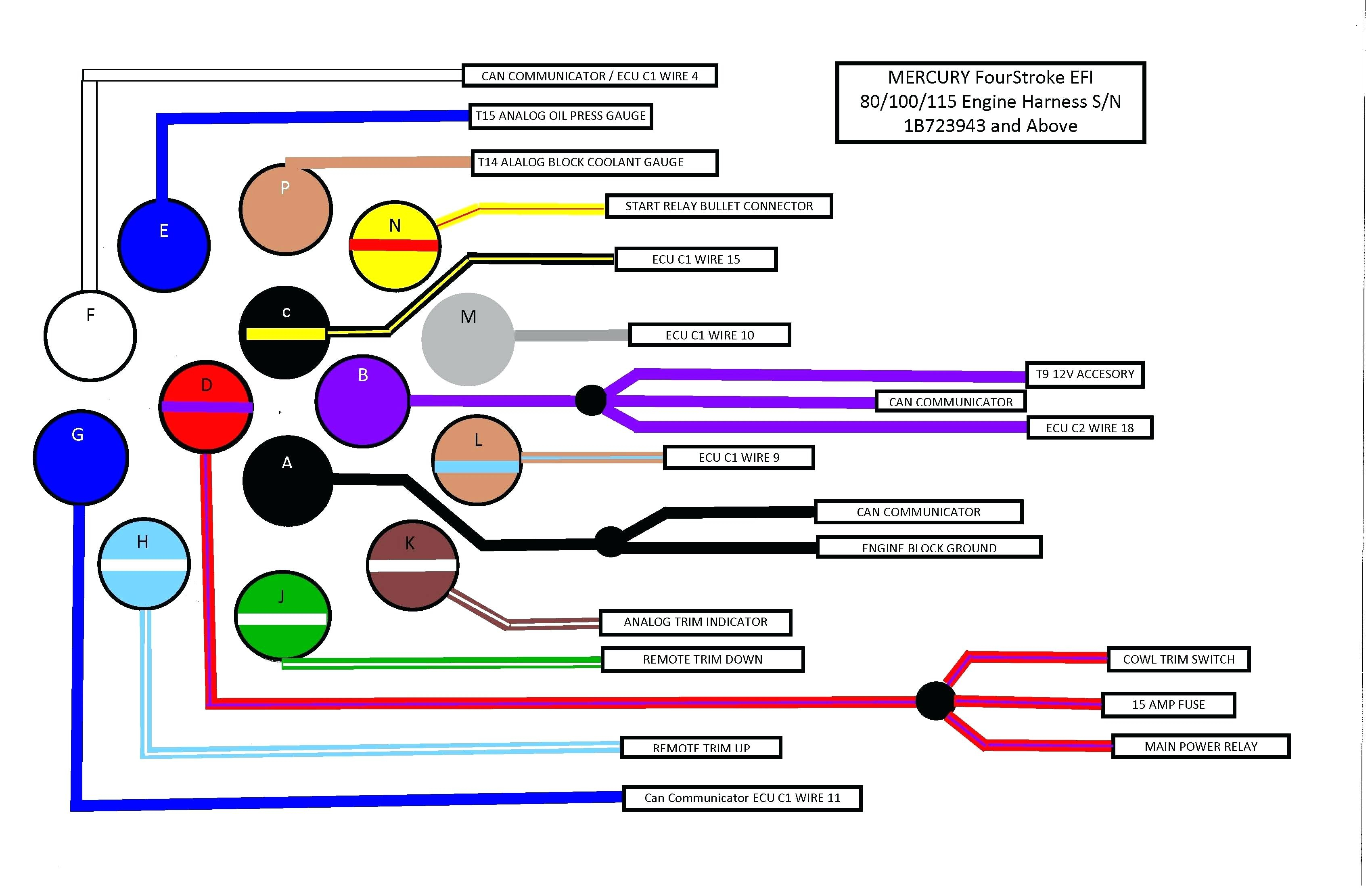
Mercury 8 Pin Wiring Harness Diagram
Let's dive into the world of Mercury 8-pin wiring harnesses. These unassuming bundles of wires are the unsung heroes behind many essential functions in older Mercury vehicles. Understanding their diagram isn't just about abstract knowledge; it's about empowering you to diagnose, repair, and even modify your classic ride with confidence. This article will break down the complexity into manageable chunks, giving you the tools you need to tackle those wiring gremlins. We assume you have some familiarity with basic automotive electrical principles, but we'll define key terms along the way.
Why Understanding the 8-Pin Wiring Harness Diagram Matters
The primary purpose of understanding an 8-pin wiring harness diagram is multifaceted:
- Repair and Restoration: Over time, wiring can corrode, break, or simply become brittle. A diagram is essential for identifying damaged wires and replacing them correctly. Without it, you're flying blind, increasing the risk of incorrect connections and further damage.
- Troubleshooting Electrical Issues: When something isn't working – a malfunctioning light, a dead sensor – a diagram helps you trace the circuit, pinpointing the source of the problem. This saves you time and money, avoiding unnecessary parts replacements.
- Modification and Upgrades: If you're adding aftermarket accessories, such as a new stereo system or performance gauges, you need to know where to tap into the existing electrical system safely and correctly. The diagram provides the roadmap.
- Learning and Education: Even if you don't plan on performing major repairs yourself, understanding the electrical system improves your overall knowledge of your vehicle's operation, making you a more informed owner.
Key Specs and Main Parts of an 8-Pin Harness
The 8-pin designation simply refers to the number of pins or terminals present in the connector. This type of harness isn’t universal across all Mercury models and years, so always confirm the diagram matches your specific vehicle. Some common applications include lighting circuits (taillights, headlights, turn signals), ignition components, and accessory power feeds. The core components you'll see in the diagram include:
- Connector Body: The physical housing that holds the pins in place.
- Pins/Terminals: The metal contacts that make the electrical connection. They are numbered, which is crucial for referencing in the diagram.
- Wires: Each wire carries a specific signal (power, ground, signal) and is typically color-coded.
- Splices: Locations where two or more wires are joined together. These are potential points of failure.
- Ground Points: Connection points to the vehicle's chassis, providing a return path for the electrical current. These are often represented by a ground symbol.
Key Specs you might find noted near the harness in a service manual include:
- Wire Gauge: Indicates the thickness of the wire (e.g., 16 AWG, 18 AWG). Thicker wires handle more current.
- Voltage Rating: The maximum voltage the wire is designed to handle.
- Current Capacity (Ampacity): The maximum current the wire can safely carry without overheating.
- Material (Conductor): Typically copper (Cu) or occasionally aluminum (Al).
- Insulation Type: PVC, XLPE, etc. The type of insulation affects the wire's resistance to heat, chemicals, and abrasion.
Deciphering the Diagram: Symbols, Lines, and Colors
A wiring harness diagram is a symbolic representation of the electrical circuit. Understanding the symbols is key to interpreting it correctly.
- Lines: Solid lines represent wires. Dashed lines might indicate shielded cables or wires that are part of a sub-assembly. The thickness of the line usually doesn't represent wire gauge; it's purely for visual clarity.
- Colors: Wire colors are crucial for identification. Common colors include Black (ground), Red (power), White, Blue, Green, Yellow, and Brown. Some wires may have stripes, indicated by abbreviations like "W/B" (White with Black stripe). Always double-check the color code legend on your specific diagram, as it can vary slightly between models.
- Symbols: These represent electrical components. Some common ones include:
- Resistor: A zig-zag line.
- Capacitor: Two parallel lines.
- Diode: A triangle pointing to a vertical line.
- Relay: A coil with a switch.
- Fuse: A line with a squiggly line or a box with the amperage rating.
- Ground: Three descending horizontal lines or a stylized "T" shape.
- Lamp/Bulb: A circle with an "X" inside.
- Switch: A line that can be open (off) or closed (on).
- Connector Representation: The connector itself is often depicted as a rectangle or a series of circles (representing the pins) with numbers indicating the pin assignments.
How an 8-Pin Wiring Harness Works
The basic principle is simple: the harness provides a structured pathway for electrical current to flow between various components. Each wire within the harness carries a specific electrical signal (voltage or ground) from one point to another. This signal might activate a relay, power a light, or transmit data from a sensor to the engine control unit (ECU). Think of it like a highway system for electricity.
When reading the diagram, follow the signal path. For example, if you're tracing the circuit for a taillight, start at the power source (often the battery, via a fuse), follow the wire through the switch (brake light switch), through the harness, and finally to the taillight bulb. The circuit is completed when the current flows from the taillight bulb to ground. A break anywhere along this path will prevent the taillight from working.
Understanding the concepts of voltage, current, and resistance (Ohm's Law: V = IR) is essential for troubleshooting. Voltage is the electrical potential difference, current is the flow of electrons, and resistance opposes the flow of current. A higher resistance in a circuit will reduce the current flow.
Real-World Use: Basic Troubleshooting Tips
Here are some basic troubleshooting tips when working with an 8-pin wiring harness:
- Visual Inspection: Start with a thorough visual inspection of the harness. Look for obvious signs of damage, such as frayed wires, cracked insulation, corroded connectors, or melted plastic.
- Continuity Testing: Use a multimeter in continuity mode to check for breaks in the wires. Disconnect the harness from both ends and place one probe on each end of the wire you want to test. The multimeter should beep or display a low resistance reading if the wire is intact.
- Voltage Testing: Use a multimeter in voltage mode to check for the presence of voltage at the correct pin. With the circuit powered on, place the black probe on a good ground and the red probe on the pin you want to test. The multimeter should display the expected voltage (e.g., 12V).
- Resistance Testing: Use a multimeter in resistance mode to check the resistance of a component or a section of the circuit. Make sure the circuit is de-energized before performing resistance testing.
- Connector Cleaning: Clean corroded connectors with electrical contact cleaner and a small brush. Apply dielectric grease to the connectors after cleaning to prevent future corrosion.
- Wire Repair: Use proper crimping tools and connectors to repair damaged wires. Soldering is also an option, but make sure to use heat shrink tubing to insulate the connection.
Safety Considerations
Working with automotive electrical systems can be dangerous. Here are some safety precautions to keep in mind:
- Disconnect the Battery: Always disconnect the negative battery cable before working on any electrical system. This will prevent accidental shorts and electrical shocks.
- Be Aware of Airbag Systems: Airbag systems can be triggered by electrical faults. Consult the service manual for the proper procedure for disabling the airbag system before working near any airbag components.
- High-Energy Ignition Systems: Avoid touching ignition components (e.g., ignition coil, spark plug wires) while the engine is running or the ignition is on. These components can generate high-voltage shocks.
- Use Proper Tools: Use insulated tools designed for electrical work.
- Work in a Well-Ventilated Area: When using solvents or cleaners, work in a well-ventilated area to avoid inhaling harmful fumes.
- Never Bypass Fuses: Fuses are designed to protect the electrical system from overcurrent. Never bypass a fuse with a wire or a higher amperage fuse.
Working with wiring harnesses requires patience, attention to detail, and a good understanding of electrical principles. Don't be afraid to consult the service manual or seek professional help if you're unsure about anything.
We have the 8-Pin Wiring Harness Diagram file available for you to download. This diagram will provide you with a detailed schematic, including wire colors, pin assignments, and component locations. This resource can be invaluable for diagnosing and repairing electrical issues in your vehicle. Download it HERE. (Replace # with actual download link)