Mercury Outboard Starter Solenoid Wiring Diagram
So, you're tackling a starter solenoid issue on your Mercury outboard? Excellent. This component is crucial for getting your engine running, and understanding its wiring is the first step toward a successful repair or upgrade. This article provides a detailed breakdown of a typical Mercury outboard starter solenoid wiring diagram, covering everything from basic function to troubleshooting tips. Having a solid grasp of this system empowers you to diagnose problems effectively and potentially save a significant amount of money on professional mechanic fees.
Why Understanding the Wiring Diagram Matters
A wiring diagram is essentially a roadmap for your electrical system. In the context of your starter solenoid, it’s invaluable for several reasons:
- Troubleshooting: When your engine won’t start, the diagram helps you pinpoint the source of the problem – is it the solenoid itself, the starting switch, the battery connection, or something else entirely?
- Repair: Damaged or corroded wires can lead to starting issues. The diagram guides you in replacing these wires correctly, ensuring proper connections and preventing future problems.
- Modifications: Planning to add a remote starter or auxiliary starting system? The diagram shows you where to tap into the existing system safely and effectively.
- Education: Even if you're not currently facing an issue, understanding the system’s layout gives you a better overall grasp of your outboard's electrical workings, enabling you to anticipate potential problems and maintain your engine more effectively.
Key Specs and Main Parts
Let’s break down the key components involved and their specifications:
Main Parts:
- Battery: Provides the initial power source (typically 12V DC). Capacity will vary by outboard motor size.
- Ignition Switch (Starting Switch): Activates the starting circuit when turned to the "Start" position.
- Starter Solenoid: An electromagnetic switch that uses a small current from the ignition switch to control a larger current to the starter motor.
- Starter Motor: The electric motor that cranks the engine until it starts.
- Ground Wire(s): Provides a return path for the electrical current, completing the circuit. Proper grounding is absolutely critical.
- Fuse/Circuit Breaker: Protects the starting circuit from overloads. Amperage rating will vary by engine size.
Key Specs to Consider:
- Voltage: Almost all smaller to mid-sized outboards operate on a 12V DC system. Larger outboards *may* use 24V or even higher. Check your engine's specifications!
- Amperage Rating: The solenoid, starter motor, and wiring must be rated to handle the high amperage draw of the starter motor. Using undersized components can lead to overheating and failure.
- Wire Gauge: The thickness of the wires (measured in AWG – American Wire Gauge) is critical. Heavier gauge wires are needed for high-current circuits like the starter. Use the recommended wire gauge for your application to prevent voltage drop and overheating.
Deciphering the Wiring Diagram: Symbols and Conventions
Understanding the symbols used in the wiring diagram is paramount. Here's a breakdown of common conventions:
- Lines: Straight lines represent wires. Thicker lines usually indicate wires carrying higher current.
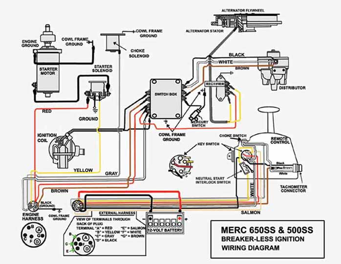
- Colors: Each wire is assigned a color, and the diagram will have a key indicating what each color represents (e.g., Red = Positive, Black = Ground, Yellow/Red = Starter Signal). Color codes are crucial for identifying wires correctly.
- Circles: Can represent various components like fuses, circuit breakers, or terminals.
- Rectangles: Often used to represent switches, relays, or the starter solenoid itself.
- Ground Symbol: A symbol resembling an inverted pyramid or a series of descending horizontal lines indicates a ground connection. A *solid* ground connection is absolutely critical for proper function.
- Component Identification: Each component is usually labeled with a code or abbreviation (e.g., "BAT" for battery, "SOL" for solenoid, "ST" for starter).
It's important to note that wiring diagrams can vary slightly depending on the model and year of your outboard. Always consult the specific diagram for *your* engine.
How the Starter Solenoid System Works
The starter solenoid acts as a high-current switch. Here’s the sequence of events:
- When you turn the ignition switch to the "Start" position, a small current flows from the battery, through the ignition switch, and to the solenoid's control circuit (the coil).
- This small current energizes the solenoid's internal electromagnet.
- The electromagnet pulls a plunger (or armature) inside the solenoid.
- This plunger mechanically closes a set of heavy-duty contacts within the solenoid, connecting the battery directly to the starter motor.
- The high current from the battery flows through the solenoid contacts to the starter motor, causing it to spin and crank the engine.
- When you release the ignition switch, the current to the solenoid's control circuit is cut off, the electromagnet de-energizes, the plunger retracts, and the connection to the starter motor is broken.
Essentially, the solenoid allows you to use a small current to control a much larger current, protecting the ignition switch from being damaged by the high amperage draw of the starter motor.
Real-World Use: Basic Troubleshooting Tips
Here are some common problems and how the wiring diagram can help you troubleshoot them:
- Engine won't crank, no click: Use a multimeter to check if you're getting 12V at the solenoid's control wire when the ignition switch is in the "Start" position. If not, the problem lies in the ignition switch, the wiring between the switch and the solenoid, or the fuse. Trace the wires using the diagram.
- Engine won't crank, clicking sound from the solenoid: This usually indicates a low battery voltage, a poor connection, or a faulty solenoid. Check the battery voltage with a multimeter. Clean and tighten all connections at the battery, solenoid, and starter. If the problem persists, the solenoid itself may be failing.
- Engine cranks slowly: This can be caused by a weak battery, corroded connections, or a failing starter motor. Check the battery voltage under load (while cranking). Clean and tighten all connections. If the problem persists, the starter motor may need to be replaced.
- Fuse blows repeatedly: Indicates a short circuit somewhere in the starting system. Use the wiring diagram to trace the circuit and look for damaged or frayed wires that might be touching ground.
Always use a multimeter to check voltage and continuity. This is the most effective way to diagnose electrical problems.
Safety Precautions
Working with electrical systems can be dangerous. Here are some important safety precautions:
- Disconnect the Battery: Always disconnect the negative (ground) cable from the battery before working on the electrical system. This prevents accidental shorts and potential electrical shocks.
- Work in a Well-Ventilated Area: Batteries can release explosive gases, especially when charging.
- Use Insulated Tools: Protect yourself from electrical shocks by using tools with insulated handles.
- Identify Hazardous Components: Be aware of the battery terminals, solenoid terminals, and starter motor terminals – these carry high current and can deliver a painful (or even deadly) shock.
- Double-Check Your Work: Before reconnecting the battery, carefully review your work to ensure all connections are tight and properly insulated.
Disclaimer: Working with electricity can be dangerous. If you are not comfortable working on electrical systems, consult a qualified marine mechanic.
We understand having a physical copy of the diagram can be very helpful. We have a standard Mercury Outboard Starter Solenoid Wiring Diagram file available for you to download and use. This file can be a useful reference during your repairs and troubleshooting.