Metra 2 Channel Adjustable Line Output Converter Wiring Diagram
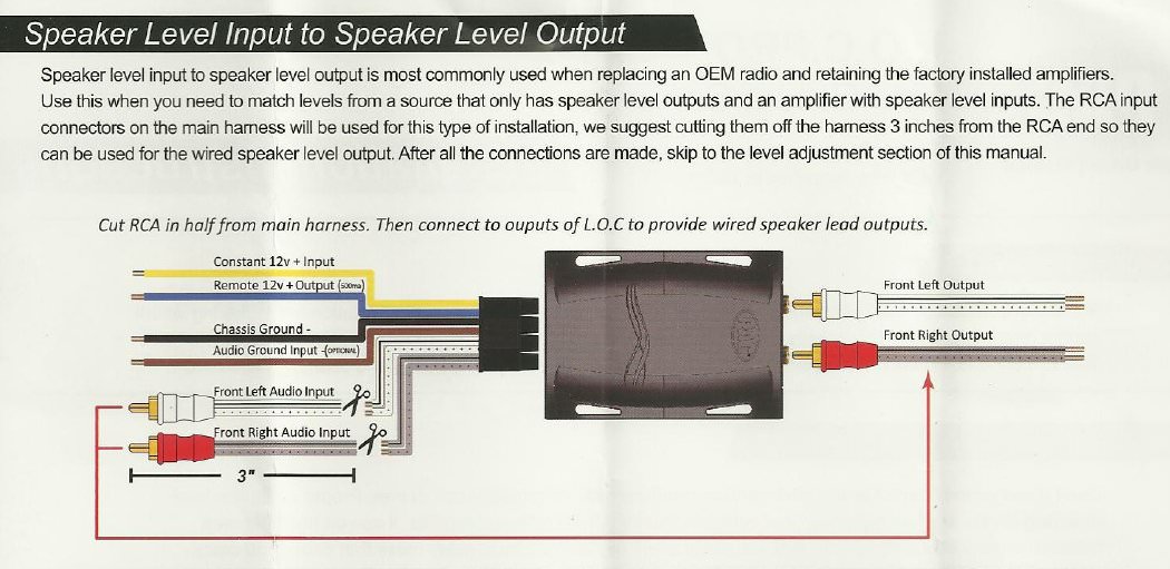
So, you're looking to upgrade your car's audio system but stuck with a factory head unit? A Metra 2-Channel Adjustable Line Output Converter (LOC) can be your best friend. This article provides a detailed look at the wiring diagram and explains how it all works. Understanding this diagram is crucial whether you're repairing an existing installation, upgrading your system, or just expanding your knowledge of car audio electronics. We have the diagram file available, and you can download it for easy reference.
Why Understanding This Diagram Matters
The primary reason to understand this wiring diagram is for a clean and safe installation of your LOC. Many factory head units don't have RCA outputs for connecting to aftermarket amplifiers. The LOC converts the high-level speaker output from the factory unit into a low-level RCA signal suitable for an amplifier. Without understanding the wiring, you risk damaging your factory stereo, your new amplifier, or both. Moreover, a proper wiring job ensures optimal audio performance, minimizing noise and distortion.
Key Specs and Main Parts of a Metra 2-Channel Adjustable LOC
Before diving into the wiring, let's cover the key specs and main components of a typical Metra 2-Channel Adjustable LOC. This will provide context to the diagram itself.
Key Specs:
- Input Channels: 2 (Left and Right speaker inputs)
- Output Channels: 2 (Left and Right RCA outputs)
- Input Voltage: Designed to handle the voltage range of typical car speaker outputs (usually up to around 50W per channel from the factory head unit).
- Output Voltage: Variable, typically adjustable to provide a clean signal for your amplifier. Usually around 0-2 Volts RMS.
- Ground Isolation: Some models include ground isolation features to help eliminate alternator whine or other noise.
- Impedance: Input impedance is high to avoid loading down the factory amplifier. Output impedance is low to efficiently drive the aftermarket amplifier.
Main Parts:
- Input Connectors: These are usually screw terminals or wire leads that accept the speaker wires from the factory head unit.
- Output Connectors: These are RCA jacks that connect to the input of your amplifier.
- Ground Terminal: A terminal for connecting the LOC to the vehicle's chassis ground.
- Gain Adjustments: Potentiometers (pots) used to adjust the output voltage of the LOC. These are crucial for matching the LOC's output level to your amplifier's input sensitivity.
- Ground Loop Isolation Switch (if equipped): A switch that can be used to isolate the ground of the LOC from the vehicle's chassis ground, which can help eliminate noise.
- Housing: The enclosure that protects the internal components of the LOC.
Understanding the Symbols in the Wiring Diagram
The wiring diagram uses standard symbols to represent different components and connections. It's essential to understand these symbols for accurate wiring.
- Solid Lines: Represent wires. Thicker lines may indicate heavier gauge wires.
- Dashed Lines: May represent shielding, or less critical connections.
- Colors: Each wire is usually color-coded. Common colors include red (power), black (ground), white (left channel), grey (right channel), and corresponding colors with stripes to differentiate positive and negative speaker wires. Always refer to the specific color code in your Metra LOC's diagram.
- Screw Terminals: Represented by a small square with a line pointing to it.
- RCA Jacks: Represented by a circle with a dot in the center and a surrounding shield symbol.
- Potentiometers (Gain Adjustments): Usually represented by a resistor symbol with an arrow through it.
- Ground Symbol: Typically a series of horizontal lines decreasing in length, connected to a vertical line.
A key thing to note is to always match the wire colors in the diagram to the corresponding wires in your car. Don't assume anything! Check the wiring diagram for your specific vehicle or use a multimeter to verify the speaker wires.
How It Works: The Signal Conversion Process
The Metra LOC's primary function is to convert the high-level speaker output from your factory head unit into a low-level RCA signal suitable for an aftermarket amplifier. Here's a breakdown of the process:
- Signal Input: The LOC receives the high-level audio signal from the factory head unit's speaker outputs. This signal is typically several volts in amplitude.
- Attenuation: The LOC uses a network of resistors to attenuate (reduce) the voltage of the high-level signal. This is crucial because amplifiers are designed to work with low-level input signals, typically around 0.2V to 2V RMS. Feeding a high-level signal directly into an amplifier's low-level input would likely cause distortion and potentially damage the amplifier.
- Impedance Matching: The LOC also performs impedance matching. The high impedance input of the LOC prevents it from loading down the factory head unit's amplifier. The low impedance output of the LOC is designed to drive the input of the aftermarket amplifier efficiently.
- Gain Adjustment: The adjustable potentiometers (gain controls) allow you to fine-tune the output voltage of the LOC. This is essential for matching the LOC's output level to the amplifier's input sensitivity. Setting the gain correctly ensures that the amplifier receives a clean signal without clipping (distortion).
- Signal Output: The LOC outputs a low-level audio signal through the RCA jacks, which can then be connected to the amplifier.
Real-World Use and Basic Troubleshooting Tips
Even with a clear wiring diagram, issues can arise during installation. Here are some common problems and how to address them:
- No Sound: Double-check all wiring connections, especially the input and output connections. Ensure the LOC is properly grounded. Verify that the factory head unit is outputting a signal to the speakers (test with another speaker if needed). Also, make sure your amplifier is powered on and functioning correctly.
- Distortion: Distortion can be caused by several factors. Ensure the gain controls on the LOC and the amplifier are properly adjusted. Clipping occurs when the signal exceeds the amplifier's input capacity. Make sure the input signal voltage from the LOC is not set to a very high value. Check the speaker wiring for shorts or loose connections.
- Noise (Alternator Whine): Alternator whine is usually caused by a ground loop. Try grounding the LOC to a different location on the vehicle's chassis. Ensure the ground connection is clean and secure. If the LOC has a ground loop isolation switch, try toggling it to see if it eliminates the noise. Sometimes, running the RCA cables away from power wires can also help reduce noise.
- Weak Signal: A weak signal can be caused by incorrect gain settings. Make sure the gain controls on the LOC are properly adjusted. Also, verify that the speaker wires are properly connected and that the factory head unit is outputting a strong signal.
- One Channel Not Working: Check the RCA connections for that channel. Ensure the speaker wire input for that channel is properly connected. Test the output of the factory head unit with another speaker to rule out a problem with the head unit itself.
Safety First: Working with Electrical Components
Working with car audio systems involves dealing with electrical components, which can be dangerous if not handled properly. Always disconnect the negative terminal of the car battery before working on any electrical connections. This prevents accidental shorts and potential damage to your vehicle's electrical system. Use proper wire connectors and crimping tools to ensure secure and reliable connections. Avoid running wires in areas where they could be pinched, cut, or exposed to extreme heat. Always use a multimeter to verify voltage and continuity before making connections. Be extremely careful when working around the car's airbag system. Disconnecting the battery will disable the airbags, but it's still best to avoid working directly on or near the airbag modules.
Specifically, remember the capacitors inside the amplifier can store charge even after the battery is disconnected. Shorting these out accidentally can be quite exciting (and potentially damaging to you or the equipment). Avoid poking around inside the amplifier unless you are experienced with electronics repair.
Important Safety Note: Never exceed the maximum input voltage specifications of the LOC. Doing so can damage the device and potentially cause a fire. Always consult the manufacturer's specifications for your specific LOC model.
Understanding the wiring diagram for your Metra 2-Channel Adjustable Line Output Converter is crucial for a safe and effective installation. By following the steps outlined in this article and paying close attention to detail, you can upgrade your car's audio system without the need for a costly professional installation. We have the diagram file available; you can download it for easy reference and happy listening!