Metra 2 Channel Line Output Converter Wiring Diagram
So, you're tackling a project that involves upgrading your car's audio system, and you've landed on needing a 2-channel line output converter (LOC). Smart choice! These little devices bridge the gap between your factory head unit and aftermarket amplifiers. A wiring diagram is absolutely crucial for a successful installation, preventing damage and ensuring optimal sound quality. We're going to dive deep into the Metra 2-channel LOC wiring diagram to give you a solid understanding of how it all works.
Why This Wiring Diagram Matters
Let's be blunt: messing with your car's electrical system without a proper understanding is a recipe for disaster. The wiring diagram is your roadmap. It’s not just about connecting wires randomly; it's about understanding signal flow, impedance matching, and ensuring proper grounding. Here’s why it's so important:
- Correct Installation: The obvious one. The diagram guides you step-by-step, minimizing the risk of wiring errors.
- Troubleshooting: If you encounter problems (e.g., no sound, distortion, engine noise), the diagram helps you pinpoint the source of the issue.
- Learning: Understanding the diagram enhances your knowledge of car audio systems, empowering you to tackle future projects with confidence.
- Preventing Damage: Incorrect wiring can fry your head unit, amplifier, or even cause electrical shorts. The diagram helps avoid costly repairs.
Key Specs and Main Parts of a 2-Channel LOC
Before we dissect the diagram, let's understand the components involved. A 2-channel LOC typically has these features:
- High-Level Inputs (Speaker Level): These accept the speaker outputs from your factory head unit. These are usually 18-22 gauge wires.
- Low-Level Outputs (RCA): These provide a low-voltage signal suitable for connecting to an aftermarket amplifier. RCA (Radio Corporation of America) connectors are standard for audio signals.
- Ground Connection: A crucial connection to the vehicle's chassis ground. This provides a common reference point for all electrical signals.
- 12V Power (Optional): Some LOCs require a 12V power source, typically for remote turn-on functionality (more on that later).
- Remote Turn-On Output (Optional): This output provides a 12V signal to turn on your amplifier when the head unit is powered on. It's essentially a relay switch.
- Gain Adjustment (Potentiometer): A small knob or screw that allows you to adjust the output level of the LOC to match the input sensitivity of your amplifier. This is sometimes referred to as a "trim pot."
Key Specs to Consider:
- Input Impedance: The impedance of the high-level inputs. This needs to be compatible with the output impedance of your head unit.
- Output Voltage: The maximum voltage the LOC can output on the RCA connections. Match this to your amplifier's input sensitivity.
- Power Handling: The maximum power the LOC can handle from the speaker outputs of the head unit. Overpowering it can damage it.
Decoding the Wiring Diagram: Symbols and Conventions
A wiring diagram is a symbolic representation of the electrical connections. Here's a breakdown of common symbols:
- Solid Lines: Represent wires. Thicker lines may indicate heavier gauge wiring.
- Dashed Lines: May represent shielded cables or less critical connections.
- Colors: Wire colors are crucial! Match the wire colors in the diagram to the actual wires in your vehicle. Common colors include:
- Red: +12V Power
- Black: Ground
- White: Left Channel Positive (+)
- Gray: Right Channel Positive (+)
- White/Black Stripe: Left Channel Negative (-)
- Gray/Black Stripe: Right Channel Negative (-)
- Squares/Rectangles: Represent components (e.g., the LOC itself, the head unit, the amplifier).
- Circles: Often used to indicate connection points or terminals.
- Ground Symbol (⏚): Indicates a connection to the vehicle's chassis ground. A good, clean ground is essential.
- RCA Connectors: Typically represented by a circle with a smaller circle inside.
- Fuse Symbol: Looks like a wavy line inside a rectangle. Always use the correct amperage fuse.
Pay close attention to the wire gauges (thickness) specified in the diagram. Using thinner wires than recommended can lead to voltage drop and overheating.
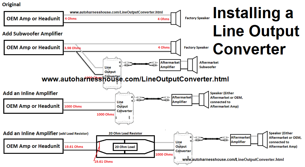
How It Works: Signal Conversion
The core function of a LOC is to convert the high-voltage, high-power speaker-level signal from your factory head unit into a low-voltage, low-power signal suitable for an aftermarket amplifier. Think of it as an attenuator, reducing the signal level without significantly altering the audio quality (ideally!).
Here's the basic signal flow:
- Speaker Output: The head unit sends amplified audio signals to the LOC's high-level inputs.
- Attenuation: Inside the LOC, resistors are used to reduce the voltage and current of the signal. This conversion process is crucial to prevent overwhelming the amplifier's input stage.
- Impedance Matching: The LOC also adjusts the impedance of the signal to better match the amplifier's input impedance. Impedance matching maximizes signal transfer and minimizes distortion.
- RCA Output: The converted, low-level signal is then output through the RCA connectors, ready to be fed into your amplifier.
- Remote Turn-On (If Applicable): Some LOCs use the presence of an audio signal on the speaker inputs to trigger a 12V output, which then turns on the amplifier. This eliminates the need to run a separate remote turn-on wire from the head unit.
Real-World Use and Basic Troubleshooting
Let's say you've wired up your LOC according to the diagram, but you're not getting any sound. Here's a basic troubleshooting checklist:
- Double-Check Connections: Ensure all wires are securely connected and properly insulated. Use butt connectors or solder and heat shrink for reliable connections.
- Verify Ground: A poor ground is the most common cause of audio problems. Make sure the ground wire is securely attached to a clean, bare metal surface on the vehicle's chassis. Scrape away any paint or rust.
- Check Fuses: Blown fuses are another common culprit. Inspect the fuses on the LOC, the amplifier, and the head unit.
- Gain Adjustment: The gain adjustment on the LOC might be set too low. Try increasing the gain gradually until you hear sound. Be careful not to over-adjust, as this can introduce distortion.
- Input Signal: Verify that the head unit is actually outputting a signal on the speaker wires you've connected to the LOC.
- Amplifier: Ensure your amplifier is powered on and functioning correctly. Check its power and ground connections, and make sure the gain is properly adjusted.
Common Problems and Solutions:
- Engine Noise (Alternator Whine): This is usually caused by a ground loop. Try grounding the LOC and amplifier to the same point on the chassis. You can also use a ground loop isolator.
- Distortion: Could be caused by clipping (overdriving) the LOC or the amplifier. Reduce the gain on both devices.
- No Remote Turn-On: If your LOC is supposed to provide a remote turn-on signal, but it's not working, check the 12V power connection to the LOC (if required). Also, some LOCs require a certain input signal level to trigger the remote turn-on.
Safety First: Working with Automotive Electrical Systems
Working on car electrical systems involves inherent risks. Here are some crucial safety precautions:
- Disconnect the Battery: Before making any electrical connections, disconnect the negative terminal of the car battery. This prevents accidental shorts and electrical shocks. This is paramount!
- Use Proper Tools: Use insulated crimpers, wire strippers, and multimeters. Avoid using household tools, as they may not be properly insulated.
- Wear Safety Glasses: Protect your eyes from flying debris.
- Work in a Well-Ventilated Area: If you're soldering, ensure adequate ventilation to avoid inhaling fumes.
- Avoid Working with Live Wires: Always double-check that the battery is disconnected before working on any wiring.
- Fuse Protection: Always use fuses of the correct amperage rating. Never use a higher amperage fuse than recommended, as this can create a fire hazard.
High-Risk Components:
- Battery: Contains corrosive acid and can produce explosive gases. Handle with care.
- Capacitors: Can store a significant electrical charge even after the battery is disconnected. Discharge them before handling.
Remember, if you're not comfortable working with electrical systems, it's best to consult a professional car audio installer. It's better to be safe than sorry.
With this information, you're well-equipped to understand and utilize the Metra 2-channel LOC wiring diagram. Take your time, follow the instructions carefully, and enjoy the improved sound quality of your upgraded audio system.