Metra Electronics 2 Channel Line Output Converter Wiring Diagram
So, you're looking to add an amplifier to your factory car stereo system, huh? That's a common upgrade, and often the best way to get the sound you really want without replacing the whole head unit. The key to making that happen cleanly, without butchering your existing wiring, is a Line Output Converter (LOC). Specifically, we're going to dive deep into the wiring diagram for a Metra Electronics 2-Channel LOC. This guide is aimed at the intermediate DIYer – someone comfortable working with car wiring, but perhaps needing a little clarification on the specifics of LOC installation.
Why Bother with This Diagram?
Why even bother with a wiring diagram? Well, several reasons. First, it's essential for a successful installation. Guesswork is a recipe for blown fuses, damaged equipment, and a whole lot of frustration. Whether you're upgrading your system for better sound quality, adding a subwoofer, or replacing a failing factory amplifier, understanding the wiring diagram is crucial. More specifically:
- Proper Installation: Prevents wiring errors that can damage your head unit, LOC, or amplifier.
- Troubleshooting: Simplifies identifying and resolving issues like poor sound quality, distortion, or no output.
- Learning: Helps you understand the underlying principles of audio signal conversion and car audio systems.
- Repairs/Modifications: If you ever need to repair or modify your installation, the diagram becomes your roadmap.
Key Specs and Main Parts
Before we get into the nitty-gritty of the diagram, let's cover the basics of a typical 2-Channel Metra LOC and its key specifications. Remember, this is a *general* overview; specific models may have slight variations.
- Input Channels: Two (Left and Right). These connect to the speaker outputs from your factory head unit.
- Output Channels: Two (Left and Right) RCA jacks. These connect to the input of your aftermarket amplifier.
- Input Voltage Range: Specifies the range of speaker-level voltage the LOC can handle. Exceeding this can damage the unit. It's usually somewhere in the range of 2-50 watts RMS per channel.
- Output Voltage: The voltage level of the RCA outputs, usually expressed in volts RMS. This dictates the signal strength fed to your amplifier. Higher output voltage can provide a cleaner signal and reduce the need to crank up the amplifier gain. Common values are 0-2V RMS, 0-4V RMS or higher, depending on the model.
- Ground Loop Isolation: Some LOCs include ground loop isolation, which helps to prevent unwanted noise (like alternator whine) from entering the audio signal.
- Remote Turn-On: Many LOCs include a remote turn-on output wire that provides a 12V signal to turn on your aftermarket amplifier when the factory stereo is powered on. This eliminates the need to find a separate ignition-switched 12V source.
- Level Adjustment (Gain Control): Potentiometers (pots) used to adjust the output level of the LOC. Allows for fine-tuning the signal to match the input sensitivity of your amplifier.
Main Parts on the LOC (and represented in the diagram):
- Speaker Wire Inputs: Connect to the factory speaker wires. Usually screw terminals or pigtail wires.
- RCA Outputs: Connect to the amplifier inputs.
- Ground Wire: Connects to a solid chassis ground.
- Remote Turn-On Wire (if equipped): Provides a 12V trigger to the amplifier.
- Potentiometers (Gain Controls): Small dials to adjust the output level of each channel.
Understanding the Symbols
The wiring diagram itself uses a set of standard symbols to represent the different components and connections. Here's a breakdown of common symbols you'll encounter:
- Solid Lines: Represent wires. The thickness might indicate wire gauge.
- Dashed Lines: May represent shielded cables (like RCA cables) or optional connections.
- Colors: Very important! Wire colors are standardized (though sometimes manufacturers deviate slightly). Pay *close* attention to the color codes to ensure you're connecting to the correct wires. Typical colors include:
- Red: +12V Constant (Battery)
- Yellow: +12V Switched (Ignition)
- Black: Ground
- White: Left Front Speaker (+)
- White/Black Stripe: Left Front Speaker (-)
- Grey: Right Front Speaker (+)
- Grey/Black Stripe: Right Front Speaker (-)
- Green: Left Rear Speaker (+)
- Green/Black Stripe: Left Rear Speaker (-)
- Purple: Right Rear Speaker (+)
- Purple/Black Stripe: Right Rear Speaker (-)
- Circles or Squares with Numbers: Represent terminal blocks or connectors, and the number indicates the pin number.
- Ground Symbol: Usually looks like an upside-down triangle or a series of lines decreasing in length.
- RCA Connector: A circle with a smaller circle inside, connected to a line (the RCA cable).
- Potentiometer (Gain Control): A resistor symbol with an arrow through it.
Always double-check the wire colors against your vehicle's wiring diagram and the LOC's documentation. Never assume!
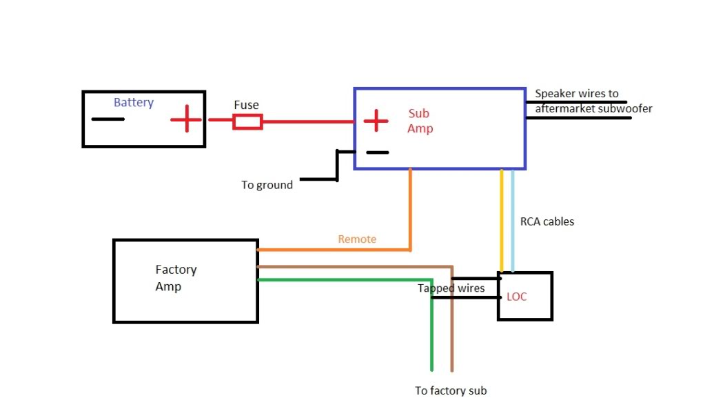
How It Works: The LOC's Role in Signal Conversion
The LOC's primary function is to convert the high-level (speaker-level) output from your factory head unit into a low-level (RCA) signal that can be accepted by an aftermarket amplifier. Factory head units are designed to power speakers directly, so their output voltage is much higher than what an amplifier's RCA inputs can handle. Without an LOC, you'd either get no sound, or a distorted, overdriven signal that could damage your amplifier.
Here's the breakdown of the process:
- Speaker Signal Input: The speaker wires from the factory head unit are connected to the LOC's input terminals.
- Voltage Attenuation: The LOC uses resistors (and sometimes transformers) to reduce the voltage of the speaker signal. This brings the voltage down to a level compatible with RCA inputs (typically around 0.2V to 4V). The gain control pots allow you to fine-tune the amount of attenuation.
- Ground Isolation (Optional): If the LOC has ground loop isolation, it prevents ground loops from forming, reducing noise.
- RCA Output: The converted low-level signal is output through the RCA jacks, ready to be connected to your amplifier.
- Remote Turn-On (Optional): When the factory radio is turned on, the LOC detects the speaker signal and generates a 12V output on the remote turn-on wire, which activates the amplifier.
Real-World Use and Basic Troubleshooting
Okay, so you've got the diagram in front of you, and you're ready to wire things up. Here are some common scenarios and troubleshooting tips:
- No Sound:
- Check Power: Ensure the LOC and amplifier are receiving power and ground. Use a multimeter to verify voltage.
- Verify Connections: Double-check all wiring connections, paying close attention to polarity (+ and -). A reversed speaker wire can cause cancellation and weak output.
- Input Signal: Confirm that the factory head unit is sending a signal to the LOC. Test with another speaker on factory wires.
- Gain Settings: Ensure the gain controls on the LOC and amplifier are properly adjusted. Start with low gain settings and gradually increase them.
- Distortion:
- Gain Staging: Reduce the gain on either the LOC or the amplifier. Too much gain at any stage can cause clipping and distortion.
- Input Overload: The LOC might be receiving too much voltage from the factory head unit. Reduce the head unit's volume.
- Speaker Impedance: Ensure your speakers have the correct impedance for your amplifier.
- Noise (Alternator Whine, Hiss):
- Ground Loop: A common culprit. Try grounding the LOC and amplifier to the same point on the chassis. Ensure the ground connection is clean and secure.
- RCA Cable Routing: Keep RCA cables away from power wires. Run them along the opposite side of the vehicle to minimize interference. Use high-quality shielded RCA cables.
- LOC with Ground Isolation: Consider using an LOC with built-in ground loop isolation.
- Remote Turn-On Issues:
- Voltage Check: Verify that the remote turn-on wire is providing 12V when the factory stereo is on.
- Connections: Double-check the connection to the amplifier's remote turn-on input.
- LOC Configuration: Some LOCs require configuration for remote turn-on functionality (e.g., a switch or jumper setting).
Safety First!
Working with car electrical systems can be dangerous. Here are some key safety precautions:
- Disconnect the Battery: *Always* disconnect the negative terminal of the battery before working on any electrical wiring. This prevents accidental shorts and electrical shocks.
- Fuse Protection: Ensure that all wiring is properly fused. Use the appropriate fuse size for the circuit.
- Wire Gauge: Use the correct gauge wire for the amperage draw of the amplifier. Undersized wiring can overheat and cause a fire.
- Proper Insulation: Protect all wiring connections with electrical tape or heat shrink tubing. This prevents shorts and corrosion.
- Avoid Sharp Edges: Route wires away from sharp edges that could damage the insulation. Use grommets to protect wires passing through metal panels.
- High Voltage Components: While the LOC itself operates at relatively low voltages, be aware of the car's electrical system, which contains high-current circuits that can be very dangerous.
Remember: If you are not comfortable working with car electrical systems, consult a professional car audio installer.
We have the Metra Electronics 2 Channel Line Output Converter wiring diagram available for download. This document includes a detailed visual representation of the connections, wire colors, and other relevant information to help you successfully install your LOC. Happy listening!