Metra Line Output Converter Wiring Diagram Pdf
So, you're diving into the world of car audio upgrades, and you've stumbled upon the need for a Metra Line Output Converter (LOC). Excellent choice! A LOC is your bridge between the factory-installed audio system and aftermarket amplifiers. This article will dissect a Metra LOC wiring diagram, turning that intimidating collection of lines and symbols into a comprehensible roadmap for audio bliss. We’ll cover everything from understanding its core function to troubleshooting common issues, all while keeping safety paramount.
Purpose of the Metra Line Output Converter Wiring Diagram
Let's be clear: the wiring diagram isn’t just a pretty picture. It’s essential for several reasons:
- Installation: Whether you're installing a new amplifier, subwoofer, or just upgrading the sound quality, the diagram shows you exactly where each wire from the LOC needs to connect to your factory speaker wires and the amplifier.
- Troubleshooting: If your audio isn't working as expected after the installation, the diagram is your primary resource for verifying correct connections. Mismatched wiring is the culprit in the majority of LOC-related audio issues.
- Repair: Sometimes, wires can become damaged or disconnected. The diagram helps you identify which wire goes where, allowing you to fix the issue quickly and efficiently.
- Learning: Even if you're not currently working on your car's audio system, understanding the diagram gives you a better grasp of how aftermarket audio components integrate with factory systems. This empowers you to make informed decisions about future upgrades.
In short, mastering this diagram prevents headaches, saves money on professional installations (if you're doing it yourself), and boosts your understanding of automotive audio systems.
Key Specs and Main Parts
Before we delve into the diagram, let's identify the core components and specifications of a typical Metra LOC. Understanding these basics will make interpreting the diagram much easier.
- Line Output Converter (LOC): The heart of the operation. It takes the high-level speaker output from your factory head unit and converts it into a low-level RCA signal suitable for aftermarket amplifiers. This is crucial because most factory radios don't have RCA outputs.
- Input Channels: Most LOCs have either two or four input channels. Two-channel LOCs are typically used for adding a subwoofer amplifier, while four-channel LOCs are used to amplify all four speakers in the car. Some LOCs accept up to 6 channels for advanced audio setups.
- Output Channels: These are the RCA outputs that connect to your amplifier. They correspond to the input channels (e.g., left front, right front, left rear, right rear).
- Ground Wire: This connects the LOC to the car's chassis ground, providing a stable electrical reference. A proper ground connection is critical for minimizing noise and ensuring optimal performance.
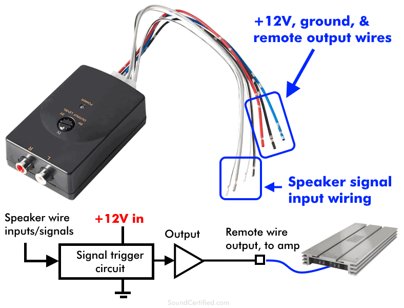
- Remote Turn-On Wire (Optional): Some LOCs have a remote turn-on output wire. This wire provides a +12V signal when the factory radio is turned on, which can be used to turn on your aftermarket amplifier. This eliminates the need to find an alternative 12V switched source in the vehicle. More advanced LOCs detect the audio signal from the head unit and automatically generate the remote turn-on signal, without requiring a dedicated remote wire.
- Gain Adjustment (Potentiometers): Many LOCs feature small dials (potentiometers) to adjust the output level. This helps you match the output voltage of the LOC to the input sensitivity of your amplifier. Proper gain staging is essential to avoid clipping and distortion.
- Specifications: Pay attention to the following specifications:
- Input Impedance: This indicates how much load the LOC places on the factory speaker outputs. A high input impedance is desirable to prevent the LOC from negatively affecting the factory system.
- Output Voltage: This is the voltage level of the RCA outputs. It should be compatible with the input voltage range of your amplifier.
- Frequency Response: This indicates the range of frequencies the LOC can accurately reproduce. A wide frequency response is desirable for optimal sound quality.
- THD (Total Harmonic Distortion): This measures the amount of distortion introduced by the LOC. A low THD is desirable for clean audio.
Symbols, Lines, and Colors in the Wiring Diagram
The wiring diagram uses standard symbols and conventions to represent different components and connections. Here's a breakdown of common elements:
- Solid Lines: These represent wires. Thicker lines might indicate wires carrying more current.
- Dashed Lines: Often represent shielded cables (like RCA cables) or less critical connections.
- Arrows: Show the direction of signal flow.
- Colors: Wires are often color-coded to match the actual wires in your car and on the LOC. Common colors include:
- Red: Typically represents positive (+) power.
- Black: Represents ground (-).
- White: Often used for left channel audio signals.
- Gray: Often used for right channel audio signals.
- Green/Purple/Blue: Usually associated with rear speakers.
- Symbols for Connectors: Squares or circles may represent connector blocks. Pins within the connector are usually numbered.
- Component Symbols: The LOC itself might be represented by a rectangle with labels indicating the input and output connections. The RCA jacks will be shown with their symbols.
- Labels: Pay close attention to labels! These tell you what each wire is for (e.g., "Left Front +," "Ground," "Remote Turn-On").
Understanding these symbols is key to accurately interpreting the diagram.
How It Works: The LOC's Role in Audio Conversion
Let's walk through the process of how the LOC converts the high-level speaker output to a low-level RCA signal.
- High-Level Input: The LOC receives the amplified speaker signal from your factory head unit. This signal typically ranges from a few volts to several volts, depending on the volume level.
- Voltage Division: The LOC uses a network of resistors to attenuate (reduce) the voltage of the speaker signal. This is the core of the conversion process.
- Isolation: The resistor network also helps to isolate the aftermarket amplifier from the factory audio system, preventing potential interference and ground loops.
- Low-Level Output: The attenuated signal is then outputted through the RCA connectors as a low-level signal, typically around 0.2V to 5V, depending on the LOC's design and gain settings.
- Ground Loop Isolation (in some models): Some LOCs incorporate additional circuitry to further reduce ground loop noise, which can manifest as a buzzing or whining sound. This can be accomplished using transformers or differential inputs.
The gain adjustment potentiometers allow you to fine-tune the amount of attenuation, ensuring that the output voltage is optimal for your amplifier. Setting the gain too high can cause clipping, while setting it too low can result in a weak signal.
Real-World Use: Basic Troubleshooting Tips
Even with a clear diagram, problems can arise. Here are some basic troubleshooting tips:
- No Sound:
- Verify that all connections are secure and correct, according to the diagram.
- Check the ground connection. A poor ground is a common culprit.
- Ensure that the remote turn-on wire (if applicable) is properly connected to a switched +12V source or is being properly triggered by the LOC's signal-sensing circuit.
- Check the fuses on your amplifier and the factory radio.
- Distorted Sound:
- Adjust the gain on the LOC and amplifier. Clipping can cause distortion.
- Check for loose or damaged speaker wires.
- Verify that the speaker impedance is compatible with your amplifier.
- Noise (Humming or Whining):
- Check the ground connection.
- Run the RCA cables away from power wires.
- Consider using a ground loop isolator.
- Incorrect Channel Output
- Double check that the input and output channels (front/rear, left/right) are correctly wired according to the diagram.
Always double-check your work and consult the diagram frequently during troubleshooting.
Safety: Addressing Risky Components
Working with car electronics can be dangerous if proper precautions aren't taken. Pay close attention to these safety concerns:
- Battery: Always disconnect the negative terminal of the car battery before working on the electrical system. This prevents accidental shorts and potential damage to your car's electronics.
- Airbags: Be aware of the location of airbags and avoid wiring near them. Accidental deployment can cause serious injury.
- Wiring Harnesses: Be careful when cutting or splicing wires. Use proper wire strippers and connectors to ensure secure and reliable connections. Avoid damaging any factory wiring.
- Fuses: Replace blown fuses with fuses of the same amperage rating. Using a higher amperage fuse can overload the circuit and cause a fire.
- Voltage: While the voltages involved in car audio are relatively low, they can still cause a shock. Avoid touching exposed wires while the system is powered on.
Safety is paramount. If you are not comfortable working with car electronics, it's best to seek professional assistance.
Remember to take your time, read the diagram carefully, and double-check your connections. With a little patience and the right knowledge, you can successfully install a Metra LOC and enjoy a significantly improved audio experience in your car.
We have a sample Metra Line Output Converter wiring diagram PDF available for download. You can use this as a guide while working on your project. Look for the link below to download it.
[Download Link - Replace with actual link when ready]