
Motorcycle Starter Relay Wiring Diagram
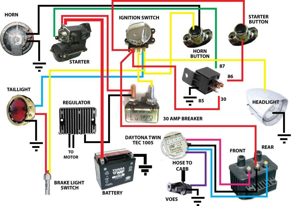
Motorcycle electrical systems, while seemingly complex at first glance, are built upon relatively simple principles. Understanding the starter relay wiring diagram is crucial for anyone venturing into motorcycle maintenance, modifications, or troubleshooting. This article will provide you with a detailed breakdown of the diagram, explaining its components, function, and practical applications. We'll be talking like trusted mechanics – cutting through the jargon and giving you the knowledge you need to confidently work on your bike.
Purpose of Understanding the Starter Relay Wiring Diagram
Why bother learning this? Several compelling reasons exist:
- Troubleshooting Starting Issues: The most common use. If your bike cranks weakly or not at all, the starter relay and its associated wiring are prime suspects. The diagram allows you to trace the circuit, identify faulty connections, and test components.
- Customization and Modifications: Adding aftermarket accessories, like alarms or remote starters, often requires interfacing with the starting circuit. Understanding the diagram ensures you're connecting everything correctly and safely.
- Learning Motorcycle Electrical Fundamentals: The starter circuit is a foundational part of the overall electrical system. Mastering this provides a solid base for understanding more complex systems, like fuel injection and ignition.
- Repair and Restoration: Replacing a damaged starter relay or repairing damaged wiring becomes much easier with a clear diagram to guide you.
- Preventative Maintenance: Regular inspection of wiring and connections, guided by the diagram, can prevent future starting problems and costly repairs.
Key Specs and Main Parts
Let's break down the essential components of a typical motorcycle starter relay circuit:
Main Components:
- Battery: The power source for the entire electrical system. It provides the high current needed to crank the engine. Look for specifications regarding its voltage (typically 12V in most motorcycles) and cold cranking amps (CCA).
- Ignition Switch: A multi-position switch that controls power to various circuits, including the starting circuit.
- Start Button: When pressed, it completes the control circuit to the starter relay, activating it.
- Clutch Switch (or Neutral Switch): A safety switch that prevents the starter from engaging unless the clutch is pulled in (or the bike is in neutral). This is crucial to prevent accidental starts while in gear.
- Starter Relay (Solenoid): An electromagnetic switch that handles the high current required by the starter motor. It's a high-ampere rated switch. It uses a low-current control signal to switch a high-current circuit.
- Starter Motor: An electric motor that turns the engine over, initiating the combustion process.
- Ground Connections: A properly grounded system is *essential*. These connections provide a return path for the electrical current to the battery.
Key Specifications:
- Voltage (V): The electrical potential difference. Most motorcycle systems operate at 12V DC.
- Current (Amps, A): The flow of electrical charge. The starter motor draws a significant amount of current (typically 50-200 amps) during cranking.
- Resistance (Ohms, Ω): The opposition to the flow of current. High resistance in wiring or connections can cause voltage drops and prevent the starter from working properly.
- Wire Gauge (AWG): The thickness of the wires. Thicker wires are needed to handle higher currents. Typically, the wire from the starter relay to the starter motor will be very thick (e.g., 8 AWG or thicker) due to the high current draw.
Understanding Wiring Diagram Symbols
Wiring diagrams use standardized symbols to represent electrical components and connections. Here's a breakdown of common symbols you'll encounter in a starter relay wiring diagram:
- Solid Lines: Represent wires. Thicker lines generally indicate wires carrying higher currents.
- Dashed Lines: May represent shielding or connections that are not directly part of the main circuit.
- Colors: Wires are often color-coded to help identify them. Common colors include red (power), black (ground), and various other colors for specific functions (e.g., blue for headlight, yellow for turn signals). You'll want to consult the specific wiring diagram for your motorcycle model to understand the color codes used.
- Battery Symbol: Two unequal parallel lines, the longer one representing the positive (+) terminal and the shorter one representing the negative (-) terminal.
- Ground Symbol: Usually a series of horizontal lines, decreasing in length.
- Switch Symbol: A break in the line with a pivoting arm. The position of the arm indicates whether the switch is open (circuit broken) or closed (circuit completed).
- Relay Symbol: A coil representing the relay's electromagnet and a switch representing the contacts that are opened or closed when the relay is activated.
- Motor Symbol: A circle with an "M" inside.
- Fuse Symbol: A squiggly line inside a rectangle. Fuses protect the circuit from overcurrent.
Key Color Codes (General): Note that this can vary by manufacturer and year.
- Red: Positive (+) battery terminal
- Black: Ground (-) battery terminal
- Green: Often used for ground, but not always.
- Consult the service manual for *your* specific motorcycle model for accurate color-coding information.
How the Starter Relay Circuit Works
Here's a step-by-step explanation of how the starter relay circuit functions:
- Key On: Turning the ignition switch to the "ON" position provides power to various circuits, including the starting circuit.
- Clutch/Neutral Safety: The clutch switch (or neutral switch) must be closed. This happens when you pull the clutch lever in (if in gear) or when the bike is in neutral. This completes part of the control circuit to the starter relay.
- Start Button Activation: Pressing the start button completes the low-current control circuit to the starter relay's coil.
- Relay Activation: When the control circuit is complete, current flows through the starter relay's coil, creating an electromagnetic field. This field pulls the relay's internal switch (the contacts) closed.
- High-Current Circuit Completion: Closing the relay's contacts completes the high-current circuit between the battery and the starter motor.
- Starter Motor Engagement: The starter motor receives power and begins to turn the engine over.
- Engine Start: Once the engine starts, the start button is released, interrupting the control circuit, and the starter motor disengages.
Real-World Use: Basic Troubleshooting Tips
Here are some basic troubleshooting steps you can take using the wiring diagram:
- No Cranking: If the starter motor doesn't turn at all:
- Check the battery voltage. Is it fully charged?
- Check the main fuse and starter relay fuse. Are they blown?
- Check the starter relay connections. Are they clean and tight?
- Test the starter relay. Use a multimeter to check for voltage at the relay's coil when the start button is pressed. If there's voltage, the relay may be faulty.
- Check the starter motor connections. Are they clean and tight?
- Weak Cranking: If the starter motor turns slowly:
- Check the battery voltage. A low battery can cause weak cranking.
- Check the battery terminals and ground connections. Clean and tighten them if necessary.
- Check for excessive voltage drop in the starter circuit. Use a multimeter to measure the voltage at the starter motor while cranking. A significant voltage drop (more than 1 volt) indicates a problem.
- Clicking Sound: If you hear a clicking sound from the starter relay but the starter motor doesn't turn:
- The starter relay may be faulty. Its contacts may be worn or corroded.
- The starter motor may be faulty. It may be drawing too much current.
Remember to always consult your motorcycle's service manual for specific troubleshooting procedures and diagnostic information.
Safety Precautions
Working with motorcycle electrical systems involves certain risks. Keep these points in mind:
- Battery: Disconnect the negative (-) battery terminal before working on the electrical system to prevent short circuits.
- High Current: The starter motor circuit carries high current. Avoid short-circuiting the battery, as this can cause sparks, heat, and potential damage to components or injury.
- Fuses: Never replace a blown fuse with one of a higher amperage rating. This can overload the circuit and cause a fire.
- Wiring: Inspect wiring for damage, such as frayed insulation or corroded connections. Repair or replace damaged wiring as needed.
- Knowledge is Key: If you're unsure about any aspect of the electrical system, consult a qualified motorcycle mechanic. Don't guess!
Important Note: Incorrect wiring can damage your motorcycle's electrical system, and in some cases, can even be a fire hazard. Double-check all connections before applying power.
By understanding the starter relay wiring diagram and following safe practices, you can confidently diagnose and repair starting problems on your motorcycle. Remember to always consult your motorcycle's service manual for specific information about your model.
We have a generic starter relay wiring diagram file available for download. It can serve as a helpful visual aid while you're working. Contact us, and we'll happily provide it to you.