Murray Riding Lawn Mower Drive Belt Diagram
So, you're looking to tackle a drive belt replacement on your Murray riding lawn mower? Smart move. Understanding the drive belt system and having the correct diagram is absolutely crucial. Whether you're dealing with a snapped belt, slippage issues, or just preventive maintenance, this guide will break down everything you need to know to diagnose and fix those problems.
Purpose of a Murray Riding Lawn Mower Drive Belt Diagram
Why bother with a diagram in the first place? Well, a drive belt diagram isn't just a pretty picture; it's your roadmap to understanding the power transmission system in your Murray mower. It serves several key purposes:
- Accurate Belt Routing: The primary purpose is to show you the correct routing path of the drive belt. Mowers often have complex layouts involving multiple pulleys and idlers. Incorrect routing will lead to malfunction and premature belt wear.
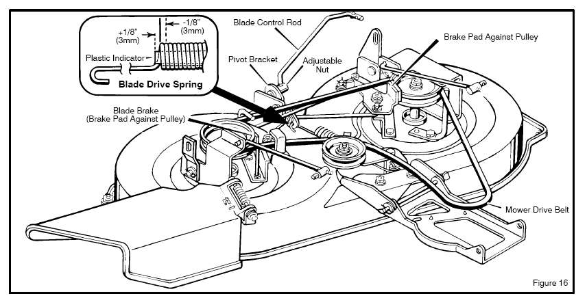
- Component Identification: The diagram identifies key components like the engine pulley, transmission pulley, idler pulleys, and any tensioning mechanisms.
- Troubleshooting: When you're experiencing problems like belt slippage or uneven cutting, the diagram helps you visually inspect the system and identify potential issues. Is a pulley misaligned? Is the tensioner working correctly? The diagram offers a starting point.
- Part Replacement: If you need to replace a pulley or idler, the diagram helps you identify the correct replacement part based on its location within the system.
- Preventative Maintenance: Using the diagram, you can periodically inspect the belt and pulleys for wear and tear, allowing you to perform preventative maintenance and avoid unexpected breakdowns.
Key Specs and Main Parts
Before diving into the diagram itself, let's cover the critical components involved in the drive system of a Murray riding mower. Keep in mind that specific layouts and parts may vary slightly depending on the model year, engine size, and transmission type of your mower.
Main Parts:
- Engine Pulley (Drive Pulley): Mounted directly on the engine's crankshaft, this pulley receives power from the engine and transmits it to the drive belt. The diameter of this pulley is crucial because it directly affects the speed of the transmission.
- Drive Belt: The heart of the system. Typically a V-belt or a cogged belt, it's responsible for transferring power from the engine pulley to the transmission pulley. The belt's length and width are critical specifications.
- Transmission Pulley (Driven Pulley): Located on the transmission input shaft, this pulley receives power from the drive belt and turns the transmission.
- Idler Pulleys: These pulleys don't directly transmit power but guide and tension the drive belt. There can be one or more idler pulleys.
- Tensioner Pulley: A specific type of idler pulley that's spring-loaded or adjustable to maintain the correct tension on the drive belt. Proper tension is essential for preventing slippage and ensuring efficient power transfer.
- Tensioner Spring: Provides the force that keeps the tensioner pulley engaged.
- Belt Keepers/Guards: Metal brackets or plates that prevent the belt from derailing from the pulleys.
Key Specs to Know:
- Belt Length: Critical for proper operation. Too short, and you can't install it. Too long, and it will slip.
- Belt Width: Belts come in different widths; using the incorrect width can cause premature wear or slippage.
- Belt Type: V-belt or Cogged (toothed) belt. The diagram will often specify the required type.
- Pulley Diameters: While you might not need to replace these often, knowing the engine and transmission pulley diameters can help you understand the drive ratio and diagnose speed-related issues.
Decoding the Symbols in Your Diagram
Diagrams aren't always straightforward, especially if you're not used to reading them. Let's decode the common symbols you'll encounter in a Murray drive belt diagram.
- Solid Lines: Usually represent the drive belt itself. The thickness of the line might indicate the belt's width.
- Dashed Lines: Often represent the path of the belt behind or underneath other components. They show how the belt snakes around hidden areas.
- Circles: These typically represent pulleys. The size of the circle might be proportional to the pulley's diameter (though not always, so double-check!).
- Arrows: Indicate the direction of rotation of the pulleys and the direction of belt travel. This is crucial for verifying that you've routed the belt correctly.
- Rectangles/Squares: May represent brackets, guards, or other structural components that are relevant to the belt's routing.
- Icons: Some diagrams use icons to represent specific components like the engine, transmission, or tensioner mechanism. A spring icon, for example, clearly indicates the location of the tensioner spring.
- Labels: Pay close attention to the labels! Each component should be clearly labeled with its name (e.g., "Engine Pulley," "Tensioner Pulley") or a part number.
Color-coding is less common in these diagrams than in, say, electrical diagrams. However, if your diagram *does* use color:
- Black: Usually represents standard components or the default path.
- Red: May highlight the drive belt itself for emphasis, or point to a specific area of concern.
- Blue/Green: May indicate alternative routing options or highlight specific types of components (e.g., all idler pulleys might be blue).
How It Works: The Drive Belt System in Action
The principle is simple: the engine's rotational force is transferred to the wheels via the drive belt. But let's break down the sequence:
- The engine cranks and rotates the engine pulley.
- The drive belt, which is wrapped tightly around the engine pulley, is pulled into motion.
- The belt then travels along its prescribed path, guided by the idler pulleys, until it reaches the transmission pulley.
- As the transmission pulley rotates, it engages the transmission.
- The transmission then transfers the rotational force to the axles, turning the wheels and propelling the mower forward (or backward).
- The tensioner pulley plays a crucial role by maintaining constant tension on the belt. This ensures that the belt doesn't slip and that power is transferred efficiently. When you engage the drive lever, the tensioner pulley typically moves *away* from the belt, tightening it and engaging the drive system. Disengaging the lever releases the tensioner, loosening the belt and stopping the mower.
The gear ratio between the engine pulley and the transmission pulley determines the speed and torque delivered to the wheels. A smaller engine pulley relative to the transmission pulley will result in higher torque but lower speed, and vice versa.
Real-World Use: Basic Troubleshooting Tips
Okay, belt diagram in hand, you're ready to tackle that stubborn mower. Here are some common issues and how the diagram can help:
- Belt Slippage: The most common problem. Refer to the diagram to check the tensioner pulley. Is it moving freely? Is the tensioner spring intact and providing adequate tension? Also, inspect the belt itself for wear, cracks, or glazing. A worn belt will slip even with proper tension. Misalignment of any pulley will cause slippage and premature wear.
- Belt Snapping: Often caused by excessive wear, misalignment, or a seized pulley. Use the diagram to identify all pulleys in the system and ensure they rotate freely. A stuck pulley will put immense stress on the belt, leading to breakage. Also, check for sharp edges or obstructions that could be rubbing against the belt.
- Uneven Cutting: While not always a drive belt issue, a slipping belt can cause inconsistent blade speed. Verify that the drive belt is properly engaged and not slipping, especially under load (e.g., when cutting thick grass).
- Difficulty Engaging Drive: If the drive lever is difficult to engage or the mower doesn't move when engaged, the problem might be with the tensioner mechanism. The diagram will help you identify the components involved in the tensioner system (e.g., the lever, linkage, spring) and diagnose the issue.
- Strange Noises: Squealing or chirping noises often indicate belt slippage. Grinding or rattling noises might point to a worn or damaged pulley. Use the diagram to visually inspect each pulley and check for play or damage.
Safety First!
Working on machinery involves inherent risks. Keep these safety tips in mind:
- Disconnect the Spark Plug: Before doing any work on the mower, disconnect the spark plug wire to prevent accidental starting.
- Wear Safety Glasses: Protect your eyes from debris.
- Wear Gloves: Protect your hands from sharp edges and grease.
- Never Work on a Running Mower: Obvious, but worth repeating.
- Be Mindful of Rotating Parts: Even with the engine off, some parts may rotate freely due to momentum. Keep your hands clear.
- Tensioner Springs are Potentially Dangerous: These springs are under high tension and can cause injury if released suddenly. Use caution when working around them, and consider using a spring compressor if necessary.
- Sharp Blades: Even when not powered, the mower blades can cause injury. Be careful when working near the mower deck.
Finally, remember to consult your mower's owner's manual for specific safety instructions and procedures.
We understand how vital it is to have the correct resources when doing this kind of work. That's why we have a detailed Murray Riding Lawn Mower Drive Belt Diagram available for you to download. It will provide you with a comprehensive visual aid for your repair or maintenance project. Please contact us if you need it!