Nissan 3 Wire Camshaft Position Sensor Wiring Harness
Hey there, fellow gearheads! Today, we're diving deep into the world of Nissan's 3-wire Camshaft Position (CMP) Sensor wiring harness. Understanding this often-overlooked component is crucial for accurate engine timing, optimal performance, and diagnosing a whole host of driveability issues. Whether you're tackling a repair, planning a modification, or simply expanding your automotive knowledge, this guide will break down the intricacies of the 3-wire CMP sensor and its wiring. We've got a detailed diagram ready for you – just hang tight and we'll tell you how to grab it at the end.
Purpose
Why should you care about the CMP sensor wiring harness? Well, imagine trying to play a symphony with instruments wildly out of sync. That’s essentially what happens when the CMP sensor isn't communicating properly with the Engine Control Unit (ECU). The CMP sensor provides the ECU with critical information about the position of the camshaft, which in turn is used to determine the exact moment to fire the spark plugs and inject fuel. A faulty sensor or wiring harness can lead to:
- Poor engine performance: Stumbling, hesitation, or lack of power.
- Difficult starting: Prolonged cranking or complete refusal to start.
- Check Engine Light (CEL): Illumination of the CEL with codes related to CMP sensor issues.
- Reduced fuel economy: Inefficient combustion due to mistimed events.
- Potential engine damage: In extreme cases, severe timing errors can damage engine components.
Understanding the wiring harness allows for informed troubleshooting, accurate repairs, and even custom modifications that might involve sensor relocation or signal manipulation.
Key Specs and Main Parts
The typical Nissan 3-wire CMP sensor wiring harness consists of the following key elements:
- CMP Sensor: The sensor itself, typically a Hall-effect sensor or a magnetic reluctance sensor.
- Connector: The electrical connector that plugs directly into the CMP sensor. This is usually a 3-pin connector.
- Wiring: Three wires, each serving a specific purpose. These are usually color-coded for easy identification.
- ECU Connection: The point where the wires connect to the ECU, either directly or through an intermediate harness.
- Ground Point: A dedicated ground connection point, usually bolted to the engine block or chassis.
The three wires typically carry the following signals:
- Power Supply (Typically 12V or 5V): Provides the necessary voltage for the sensor to operate.
- Ground: Provides a return path for the electrical current.
- Signal Output: This wire transmits the position information from the sensor to the ECU. This signal is typically a pulsed voltage or a square wave.
Hall-effect sensors use a magnetic field and a semiconductor to produce a voltage signal. Magnetic reluctance sensors generate a signal based on changes in magnetic flux as the camshaft rotates.
Symbols
Understanding the symbols in a wiring diagram is critical. Here's a breakdown:
- Solid Lines: Represent wires. Thicker lines might indicate wires carrying more current.
- Dashed Lines: Usually represent shielded wires or ground connections.
- Color Codes: Wires are almost always color-coded. Common examples include:
- Red: Power supply (+12V or +5V)
- Black: Ground
- Blue/Yellow/Green/White: Signal wires (these can vary depending on the specific Nissan model and year)
- Connector Symbols: Represent the physical connectors that join the wires together. These can be shown as simple rectangles or more detailed representations of the actual connector shape.
- Ground Symbol: Usually a series of downward-pointing lines or a triangle, indicating a connection to the vehicle's chassis ground.
- ECU Symbol: Often a rectangle or a square with pins representing the ECU's input/output terminals.
- Resistor Symbol (Zig-zag line): May be included in some circuits, indicating a specific resistance value.
Understanding these symbols allows you to trace the circuit, identify potential problem areas, and perform accurate testing.
How It Works
The CMP sensor works in conjunction with a toothed wheel or reluctor ring attached to the camshaft. As the camshaft rotates, the teeth pass by the sensor. Depending on the sensor type, this changes the magnetic field (Hall-effect) or magnetic flux (magnetic reluctance) near the sensor. This change generates a voltage pulse or a square wave signal. The frequency and pattern of this signal directly correlate to the camshaft's position and speed.
The ECU interprets this signal and uses it to precisely time the fuel injection and ignition events. The CMP sensor signal is often used in conjunction with the Crankshaft Position (CKP) sensor signal to provide even more accurate engine timing information. The CKP sensor monitors the crankshaft's position and speed.
Without a properly functioning CMP sensor, the ECU can’t accurately determine the camshaft’s position, leading to the performance issues we discussed earlier.
Real-World Use – Basic Troubleshooting Tips
Here are some basic troubleshooting steps you can take if you suspect a problem with the CMP sensor or its wiring:
- Visual Inspection: Check the wiring harness for any signs of damage, such as frayed wires, cracked insulation, or corroded connectors. Pay close attention to the connector at the sensor and the ECU connection.
- Continuity Test: Use a multimeter to check the continuity of each wire in the harness. Disconnect the harness from both the sensor and the ECU (or ground) before testing to avoid damaging the components. You should have near-zero resistance on each wire.
- Voltage Test: With the ignition on, use a multimeter to check for the presence of power supply voltage at the sensor connector. Refer to your vehicle's service manual for the correct voltage specification (typically 5V or 12V).
- Signal Test: Use an oscilloscope or a multimeter with frequency measurement capability to check the signal output from the sensor while the engine is cranking or running. The signal should be a pulsed voltage or a square wave with a frequency that varies with engine speed. Caution: This test requires some familiarity with oscilloscopes and electrical testing procedures.
- Scan Tool: Use an OBD-II scan tool to read any diagnostic trouble codes (DTCs) related to the CMP sensor. Common codes include P0340 (Camshaft Position Sensor Circuit Malfunction), P0341 (Camshaft Position Sensor Circuit Range/Performance), and related codes.
If you find any issues with the wiring harness, repair or replace it as needed. Consider using dielectric grease on the connector pins to prevent corrosion and ensure a good electrical connection.
Safety
Working with electrical systems can be dangerous. Here are some important safety precautions:
- Disconnect the Battery: Always disconnect the negative battery terminal before working on any electrical components. This prevents accidental short circuits and potential electrical shocks.
- Use Proper Tools: Use properly insulated tools designed for automotive electrical work.
- Avoid Water: Never work on electrical systems in wet conditions.
- Be Careful with High-Voltage Components: The ignition system, including the ignition coils, can generate high voltages. Avoid touching these components while the engine is running or cranking.
- ECU Sensitivity: The ECU is a sensitive electronic device. Avoid static discharge and protect it from physical damage.
Important: Always consult your vehicle's service manual for specific safety precautions and repair procedures. If you're not comfortable working on electrical systems, it's best to seek the assistance of a qualified mechanic.
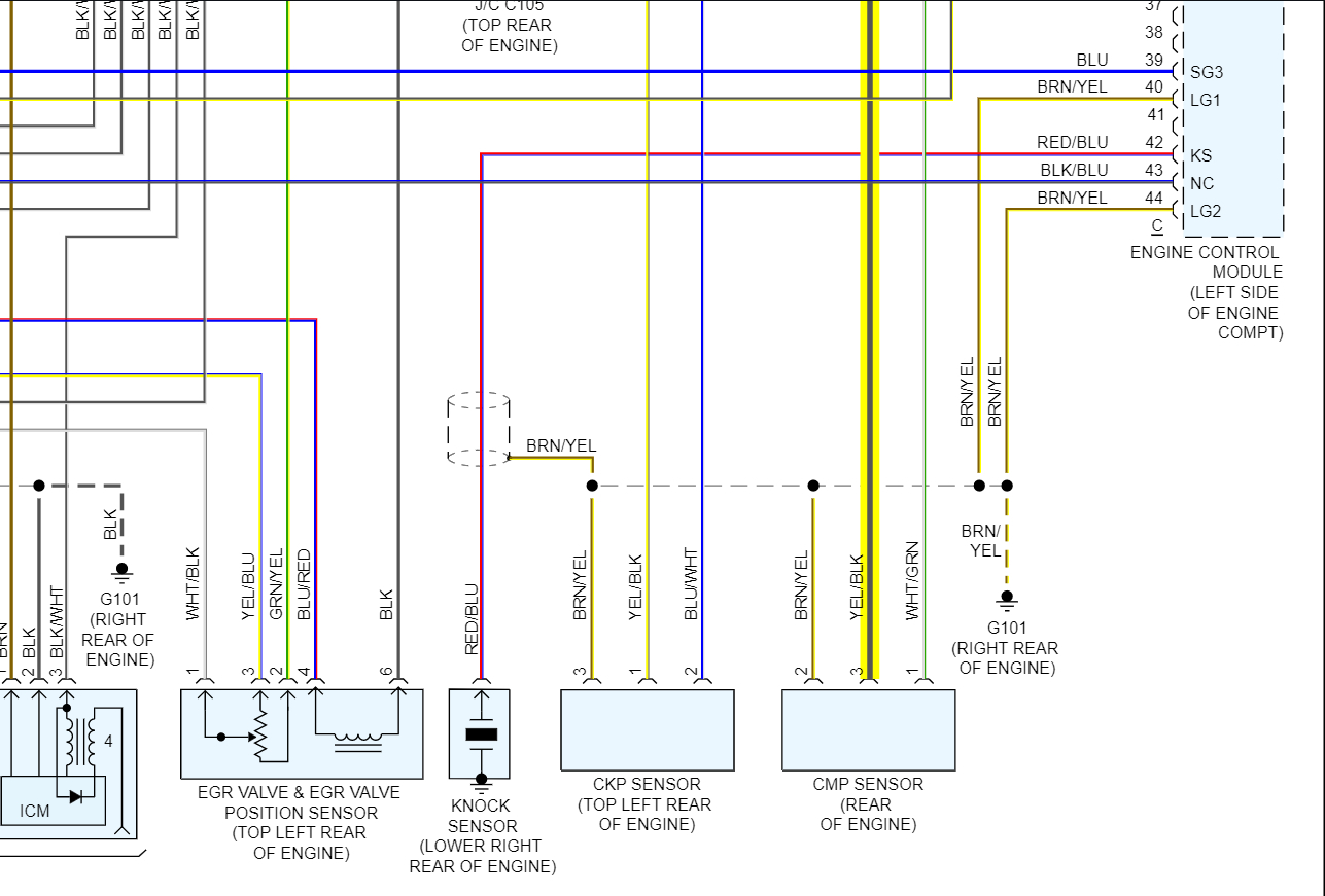
This guide provides a general overview of the Nissan 3-wire CMP sensor wiring harness. Specific details may vary depending on the year, make, and model of your vehicle. Always refer to the appropriate wiring diagram for your specific application.
And now, as promised: the detailed wiring diagram we've been talking about is ready for you! Simply follow [instructions on how to download/access the file]. This diagram will provide you with the specific wire colors, connector locations, and circuit details for a range of Nissan models. Happy wrenching!