
Nissan 5 Wire Maf Sensor Wiring Diagram
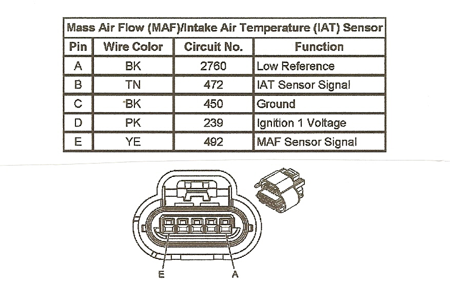
So, you're diving into the world of Nissan Mass Air Flow (MAF) sensors, specifically the 5-wire variant. Good on you! Understanding these sensors is crucial for diagnosing and resolving a whole host of engine performance issues. This article isn't just a wiring diagram explanation; it's your guide to understanding the sensor's function, its wiring intricacies, and how to troubleshoot it effectively. Whether you're chasing down a pesky lean code, prepping for a modification, or just expanding your automotive knowledge, you've come to the right place.
Why Bother with the 5-Wire MAF Sensor Wiring Diagram?
Why learn about this specific wiring diagram? Well, the 5-wire MAF sensor is a common sight in many Nissan vehicles. It plays a critical role in your engine's operation. Access to a clear wiring diagram allows you to:
- Diagnose Electrical Problems: Identify broken wires, shorts, or open circuits in the MAF sensor circuit. This is crucial for fixing issues that can trigger a check engine light and degrade performance.
- Perform Repairs: Accurately rewire a damaged connector, replace a faulty sensor, or repair damaged wiring harness sections with confidence.
- Understand Sensor Function: Gain a deeper understanding of how the MAF sensor works, making it easier to diagnose and resolve related engine issues.
- Modify and Upgrade: If you're planning on engine modifications, understanding the MAF sensor wiring is crucial for ensuring proper fuel delivery and avoiding engine damage. For example, you might need to scale the MAF sensor values in your ECU after installing a larger MAF housing.
- Prevent Misdiagnosis: Avoid throwing parts at a problem without understanding the root cause. A faulty MAF sensor can mimic other issues, leading to unnecessary repairs.
In short, the wiring diagram is your roadmap to understanding and resolving problems related to the MAF sensor. It saves you time, money, and frustration.
Key Specs and Main Parts of a Nissan 5-Wire MAF Sensor
Before we dive into the wiring diagram itself, let's cover the basics of the 5-wire MAF sensor:
- Sensor Element: This is the heart of the MAF sensor. It's a heated element (usually a hot wire or hot film) that measures the mass of air flowing into the engine. As air flows past the heated element, it cools it down. The sensor's electronics then adjust the current flow to maintain a constant temperature. The amount of current required is directly proportional to the mass of air flow.
- Housing: The housing channels the air through the sensor element. It's designed to minimize turbulence and ensure accurate measurements.
- Connector: This is where the wiring harness plugs into the sensor. It provides the electrical connections for power, ground, and the output signal.
- Electronics: These internal components process the signal from the sensor element and generate an output voltage or frequency signal that the engine control unit (ECU) can understand.
Now, let's look at the five wires themselves. While color codes can vary slightly depending on the year and model of your Nissan, the general function of each wire remains consistent:
- +12V Power (Ignition Switched): Provides power to the sensor's electronics. Typically receives power when the ignition is in the "on" position.
- Ground: Provides a common ground connection for the sensor's electronics. Ensures accurate voltage readings.
- MAF Signal Output: This is the crucial wire that sends the mass air flow signal to the ECU. The voltage on this wire varies depending on the amount of air flowing into the engine.
- Intake Air Temperature (IAT) Signal: Many 5-wire MAF sensors integrate an IAT sensor. This wire sends the intake air temperature signal to the ECU. The IAT sensor is a thermistor, meaning its resistance changes with temperature.
- IAT Ground: Provides a dedicated ground for the IAT sensor.
Understanding the Wiring Diagram Symbols
A wiring diagram is essentially a visual representation of the electrical circuit. Here's what you need to know to decipher it:
- Lines: Represent wires connecting different components. The thickness of the line doesn't usually indicate wire gauge, but rather clarity in the diagram.
- Colors: Each wire is typically represented by a specific color (e.g., Red, Black, Blue, Yellow, Green). These colors are usually abbreviated (e.g., R, B, L, Y, G). Consult the diagram's legend for the specific color codes used in your vehicle.
- Connectors: Represented by squares, circles, or other symbols. These indicate where wires connect to each other or to components. Look for connector pin numbers on the diagram for precise connection points.
- Components: The MAF sensor is typically represented by a rectangle or a similar shape with pins corresponding to the wiring connections. Other components, such as fuses, relays, and the ECU, are also represented by their respective symbols.
- Ground: Usually indicated by a symbol resembling an upside-down triangle, a series of horizontal lines getting progressively shorter, or the letters "GND".
- Voltage Source: A battery symbol or a "+" sign indicates a voltage source (e.g., +12V).
Remember to refer to the specific legend provided with your wiring diagram. Nissan wiring diagrams can vary slightly between models and years.
How a 5-Wire MAF Sensor Works
The MAF sensor's primary job is to tell the ECU how much air is entering the engine. This information is vital for calculating the correct amount of fuel to inject, ensuring optimal combustion. Here's the basic principle:
- Airflow Measurement: Air enters the engine through the intake and passes through the MAF sensor housing. The heated element inside the sensor is cooled by the incoming air.
- Current Adjustment: The sensor's electronics continuously adjust the current flowing through the heated element to maintain a constant temperature.
- Signal Generation: The amount of current required to maintain the element's temperature is directly proportional to the mass of air flowing through the sensor. This current is converted into a voltage signal.
- IAT Measurement: The integrated IAT sensor measures the temperature of the incoming air. This information is also sent to the ECU.
- ECU Interpretation: The ECU receives the MAF signal (voltage) and the IAT signal. It uses these signals, along with other sensor inputs (e.g., throttle position, engine speed), to calculate the correct amount of fuel to inject.
- Fuel Injection Adjustment: The ECU then controls the fuel injectors, injecting the precise amount of fuel needed for optimal combustion.
In essence, the MAF sensor acts as a "breathing monitor" for your engine, providing the ECU with the information it needs to keep the engine running smoothly and efficiently.
Real-World Use: Basic Troubleshooting Tips
Here are some basic troubleshooting steps you can take using the wiring diagram:
- Check for Power and Ground: Use a multimeter to verify that the MAF sensor is receiving power (typically +12V) and has a good ground connection. Refer to the wiring diagram to identify the correct pins.
- Inspect Wiring: Visually inspect the wiring harness for any signs of damage, such as broken wires, frayed insulation, or corroded connectors.
- Test the MAF Signal: With the engine running, use a multimeter or oscilloscope to monitor the MAF signal output. The voltage should change as the engine speed increases and decreases. A steady or erratic voltage reading can indicate a faulty sensor.
- Check the IAT Signal: Use a scan tool or multimeter to check the IAT sensor reading. Compare the reading to the actual intake air temperature. An inaccurate reading can indicate a faulty IAT sensor or a wiring problem.
- Scan for Codes: Use an OBD-II scanner to check for any Diagnostic Trouble Codes (DTCs) related to the MAF sensor or IAT sensor. These codes can provide valuable clues about the nature of the problem. Common codes include P0100 (MAF Circuit Malfunction), P0101 (MAF Performance), P0112 (IAT Sensor Low Input), and P0113 (IAT Sensor High Input).
Important Note: When testing electrical circuits, always use a multimeter or oscilloscope with a high impedance input to avoid damaging sensitive electronic components.
Safety First!
Working on your car can be rewarding, but safety should always be your top priority. Here are a few safety precautions to keep in mind when working with the MAF sensor and its wiring:
- Disconnect the Battery: Before working on any electrical components, disconnect the negative terminal of the battery to prevent accidental shorts and electrical shocks.
- Avoid the Airbag System: Be extremely cautious when working near the airbag system. Accidental deployment of an airbag can cause serious injury.
- Fuel System: MAF sensors are located near the fuel system. Be extra careful with heat sources and any electrical devices to avoid igniting fuel vapours.
- Use Proper Tools: Use the correct tools for the job, and ensure that they are in good condition.
- Work in a Well-Ventilated Area: When working with solvents or other chemicals, work in a well-ventilated area to avoid inhaling harmful fumes.
- Consult a Professional: If you are not comfortable working on your car, or if you are unsure about any aspect of the repair, consult a qualified mechanic.
The MAF sensor itself contains sensitive electronic components. Avoid dropping or jarring the sensor, as this can damage it.
By following these safety precautions, you can minimize the risk of injury and ensure a safe and successful repair.
We have the full Nissan 5-Wire MAF Sensor Wiring Diagram available for download. Understanding this diagram is a significant step towards mastering your vehicle's engine management system. Armed with this knowledge, you can confidently diagnose, repair, and even modify your Nissan's engine for optimal performance. Good luck!