Nissan Altima 2009 Fuse Box Diagram
Alright, let's dive into the fuse box diagram for your 2009 Nissan Altima. Whether you're troubleshooting electrical gremlins, adding aftermarket accessories, or just want to understand your car's systems better, understanding this diagram is crucial. Think of it as the roadmap to your Altima's electrical nervous system.
Purpose of the Fuse Box Diagram
Why bother learning about this? Several reasons. Firstly, for repairs. A blown fuse is often the culprit behind a non-functioning component (e.g., a dead power window, a non-starting car). The diagram tells you exactly which fuse to check. Secondly, for modifications. Adding a new amplifier, lighting system, or any electrical accessory requires tapping into existing circuits. The diagram helps you identify suitable power sources and fuse ratings. Finally, just for general understanding of your vehicle. Knowing where the fuses are and what they protect can give you a better grasp of how your car operates.
Key Specs and Main Parts of the 2009 Altima Fuse System
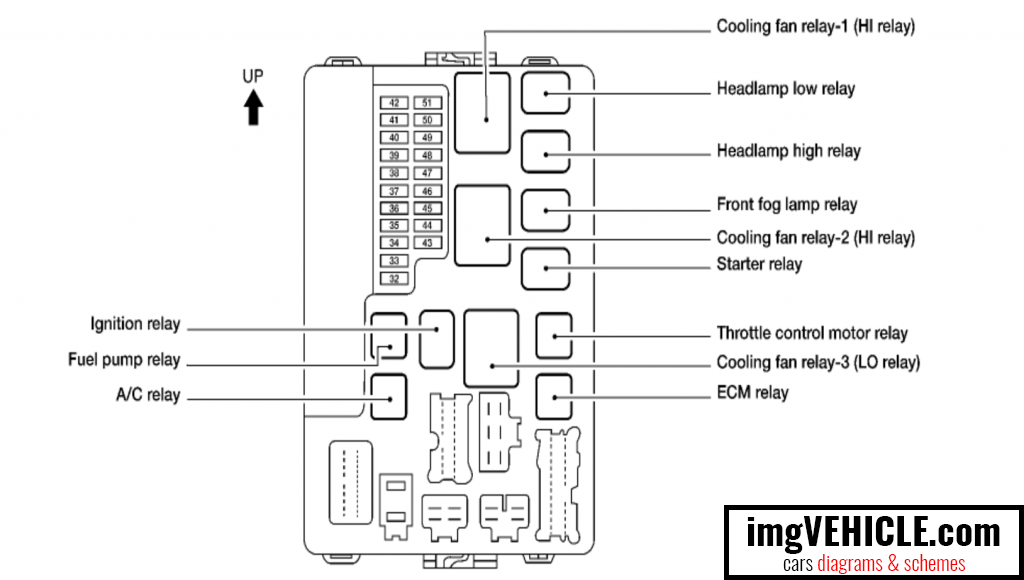
The 2009 Altima typically has two main fuse boxes: one located in the engine compartment (near the battery) and another inside the cabin, usually under the dashboard on the driver's side. Some models might have a third, smaller fuse box. Each box contains a collection of fuses and relays.
- Fuses: These are the primary safety devices. A fuse is a small, sacrificial component designed to break a circuit if the current exceeds its rated capacity, preventing damage to more expensive components. Fuses are rated in amperes (A) – the higher the number, the more current it can handle before blowing. Common ratings you'll see are 5A, 7.5A, 10A, 15A, 20A, 25A, and 30A.
- Relays: Relays are electrically operated switches. They allow a low-current circuit (like a switch on your dashboard) to control a high-current circuit (like the headlights). They're basically intermediaries, protecting the low-current circuit from overload and enabling features like automatic headlight shut-off.
- Fuse Box Cover/Diagram: This is the crucial part! The inside of the fuse box cover (or sometimes a separate sheet tucked inside) contains the diagram that maps each fuse and relay to a specific function. This is what we'll be dissecting.
Understanding Fuse Box Diagram Symbols and Markings
The diagram isn't just a random collection of lines and boxes; it's a coded representation of the electrical system. Here's a breakdown of common symbols:
- Lines: Lines represent wires or electrical connections. Thicker lines might indicate higher current capacity.
- Boxes: These generally represent fuses. Inside the box, you'll usually find a number indicating the fuse's amperage rating.
- Circles/Squares with Symbols: These often represent relays. The symbol inside (e.g., a coil, a switch) gives a clue to the relay's function (e.g., starter relay, headlight relay).
- Colors: While the diagram itself might be black and white, the color of the *actual* fuse is often an indicator of its amperage rating. This is a standard color-coding system across most vehicles:
- Yellow: 20A
- Blue: 15A
- Red: 10A
- Brown: 7.5A
- Orange: 5A
- Abbreviations: Expect to see abbreviations like "IGN" (ignition), "ACC" (accessory), "HTR" (heater), "PWR WDO" (power window), "ECM" (engine control module), "BCM" (body control module), and so on. Familiarize yourself with these common abbreviations.
- Numbers/Labels: Each fuse and relay location will have a unique identifier (e.g., "Fuse #12," "Relay C"). These identifiers are crucial for pinpointing the correct component on the diagram.
How the Fuse System Works
Think of the fuse system as a series of checkpoints on an electrical highway. Each component (lights, radio, power windows) is connected to the battery through a wire. That wire passes through a fuse. If, for any reason, the current in that wire exceeds the fuse's rating (due to a short circuit, a faulty component, or excessive load), the fuse's internal filament melts, breaking the circuit. This prevents the excessive current from reaching and potentially damaging the component or causing a fire. Relays, as mentioned earlier, act as remote-controlled switches, allowing low-current circuits to safely control high-current devices.
Real-World Use: Basic Troubleshooting Tips
Let's say your 2009 Altima's cigarette lighter (power outlet) isn't working.
- Consult the Diagram: Locate the fuse box diagram (usually on the inside of the fuse box cover). Find the fuse labeled "CIG LTR" or "Power Outlet" (or something similar). Note its location (e.g., "Fuse #23" in the cabin fuse box) and amperage rating (e.g., 15A).
- Locate the Fuse: Open the appropriate fuse box and find the fuse in the location identified by the diagram.
- Inspect the Fuse: Visually inspect the fuse. A blown fuse will have a broken filament inside the clear plastic housing. You can also use a multimeter to check for continuity (a continuous electrical path). A good fuse will show continuity; a blown fuse will not.
- Replace the Fuse: If the fuse is blown, replace it with a *new fuse of the same amperage rating*. Never use a higher amperage fuse, as this could overload the circuit and cause damage or a fire. Using a lower amperage fuse is also not recommended as it will likely blow again very quickly.
- Test: Turn the ignition on and test the cigarette lighter. If it works, you've solved the problem! If the new fuse blows immediately, there's likely a short circuit in the wiring or the cigarette lighter itself. This requires further investigation.
Safety Considerations: Handling Electrical Components
Working with electrical systems involves inherent risks. Here's what to keep in mind:
- Disconnect the Battery: Always disconnect the negative terminal of the battery before working on any electrical components. This prevents accidental short circuits and potential shocks.
- Identify Risky Components: Be especially cautious around components like the airbag system, anti-lock braking system (ABS), and the engine control module (ECM). These systems are sensitive and can be damaged by improper handling. Consult the service manual for specific precautions before working on these systems.
- Use Proper Tools: Use insulated tools designed for automotive electrical work.
- Don't Modify Fuses: Never attempt to bypass a fuse or use a higher amperage fuse than specified. This is a fire hazard.
- Seek Professional Help: If you're unsure about any aspect of the electrical system, consult a qualified mechanic.
Remember, this guide provides a general overview. Always refer to the specific fuse box diagram for your 2009 Nissan Altima model, as there might be slight variations depending on the trim level and optional equipment.
To help you get started, we have the 2009 Nissan Altima Fuse Box Diagram file ready for download. This comprehensive diagram will be invaluable for any electrical work you undertake on your vehicle.
Disclaimer: This information is for educational purposes only and should not be considered a substitute for professional automotive advice. Always consult a qualified mechanic for any repairs or modifications to your vehicle. Working with automotive electrical systems can be dangerous, and you assume all risks associated with any actions you take based on this information.