Nissan Frontier Radio Wiring Diagram
Alright, let's talk about the Nissan Frontier radio wiring diagram. If you're tackling any kind of audio upgrade, repair, or even just trying to understand how your Frontier's sound system is put together, this diagram is your best friend. Think of it as the Rosetta Stone for your truck's audio system. I've been turning wrenches for years, and trust me, even seemingly simple radio swaps can become a nightmare without the right information.
Purpose of the Radio Wiring Diagram
The primary purpose is simple: to provide a clear and concise visual representation of all the electrical connections related to your Nissan Frontier's radio. This diagram isn't just a pretty picture; it's a crucial tool for:
- Troubleshooting Audio Problems: Is your radio cutting out? Speakers not working? The diagram helps you trace wires and identify potential points of failure, like shorts or open circuits.
- Installing Aftermarket Radios: Want to upgrade to a touchscreen head unit with Apple CarPlay or Android Auto? You *need* to know which wire is for power, ground, speakers, etc. Mismatching wires can fry your new radio or worse.
- Adding Amplifiers and Speakers: Integrating aftermarket amplifiers and speakers requires tapping into the existing wiring. The diagram tells you where to tap in and ensures you're not overloading circuits.
- General Understanding of the Audio System: Even if you're not actively working on your system, the diagram provides valuable insight into how all the components work together.
Key Specs and Main Parts
A typical Nissan Frontier radio wiring diagram, especially for models from the late 1990s to the current generation, will include the following key specifications and components. Keep in mind, there can be slight variations depending on the year, trim level, and factory options. The specific file we have access to will cover the most common configurations.
Key Specs:
- Voltage: Most Frontier systems operate on a standard 12V DC system. Understanding this is critical when troubleshooting power issues.
- Impedance: Speaker impedance (typically 4 ohms) is vital when adding amplifiers or replacing speakers. Matching impedance is essential to avoid damaging your amplifier.
- Wattage: Knowing the factory radio's output wattage helps you choose appropriate replacement components. Exceeding the factory wiring's capacity can lead to overheating and fire hazards.
Main Parts Shown on the Diagram:
- Head Unit (Radio): This is the central control unit, and the diagram shows its power, ground, illumination, antenna, and speaker connections.
- Speakers: Front, rear, and sometimes tweeters or subwoofers. The diagram details the positive and negative speaker wire connections for each speaker.
- Antenna: Shows the antenna lead-in and connection to the head unit.
- Ground Points: Critical for proper operation. The diagram shows where the radio and other components are grounded to the vehicle's chassis. A poor ground can cause a multitude of electrical problems.
- Power Source: The diagram shows the power wire connecting to the vehicle's electrical system, often through a fuse.
- Fuses: Indicates the location and amperage of the fuse protecting the radio circuit. Always replace a blown fuse with one of the same amperage.
- Amplifier (if equipped): If your Frontier has a factory amplifier, it will be shown with its connections to the head unit, speakers, and power source.
- Steering Wheel Controls (if equipped): Shows the wiring for the steering wheel audio controls.
Understanding Symbols: Lines, Colors, and Icons
Decoding the symbols is key to understanding the diagram. Here's a breakdown of common symbols:
- Lines:
- Solid Lines: Represent continuous wires.
- Dashed Lines: May indicate shielded wires, optional connections, or wires that are part of a larger harness.
- Arrows: Indicate the direction of current flow.
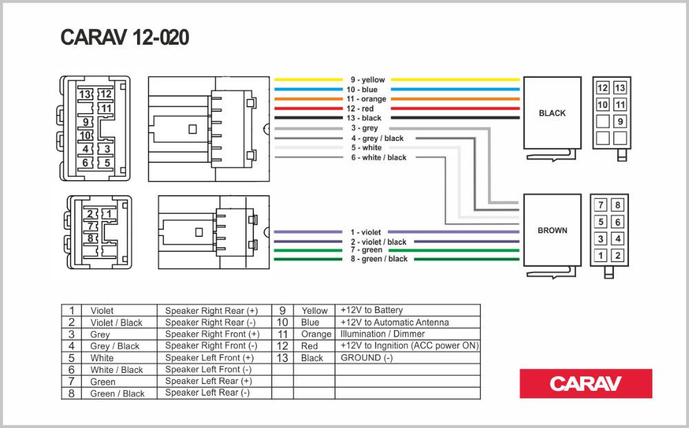
- Colors:
Colors are standardized to help you identify wires in your vehicle. Here are some common color codes:
- Red: Typically indicates a constant 12V power source.
- Yellow: Often indicates a switched 12V power source (ignition-controlled).
- Black: Ground. Always ground to a clean, unpainted metal surface.
- White: Often used for speaker wires (or a component of a speaker wire).
- Green, Blue, Gray, Violet: Used for various speaker wires and other signals.
Important Note: Color codes can vary slightly depending on the year and model. Always double-check the diagram for your specific vehicle.
- Icons:
- Ground Symbol: Looks like an upside-down triangle or a series of descending lines.
- Fuse Symbol: A squiggly line inside a rectangle.
- Connector Symbol: Shows where wires connect to a plug or connector.
- Speaker Symbol: Resembles a cone.
How It Works: Following the Circuit
The diagram illustrates how power flows from the battery, through the fuse, to the radio. From there, the radio processes audio signals and sends them to the speakers. The ground wire completes the circuit, allowing current to flow. Understanding this basic flow is essential for troubleshooting. For example, if your radio has no power, the first thing you should check is the fuse and the ground connection.
The speaker circuits are separate, with positive and negative wires running from the radio (or amplifier) to each speaker. The diagram shows which wires correspond to each speaker. Mixing up the positive and negative wires can result in out-of-phase audio, which sounds thin and lacks bass.
Real-World Use: Basic Troubleshooting Tips
Here are some basic troubleshooting tips using the radio wiring diagram:
- No Power to Radio:
- Check the fuse indicated in the diagram. Replace if blown.
- Verify the ground connection is secure and clean. Use a multimeter to check for continuity between the ground wire and the vehicle's chassis.
- Use a multimeter to check for 12V power at the radio's power wire. If there's no power, trace the wire back to the fuse box, looking for breaks or loose connections.
- One Speaker Not Working:
- Check the speaker wire connections at the radio and the speaker.
- Use a multimeter to check the speaker wire for continuity.
- Test the speaker itself by connecting it to a known working audio source (e.g., another radio or amplifier).
- Distorted Sound:
- Check the speaker wires for shorts to ground.
- Inspect the speakers for damage.
- Ensure the speaker impedance matches the amplifier's requirements.
Safety First: Risky Components
Working with automotive electrical systems can be dangerous. Here's what to watch out for:
- Battery: Disconnect the negative battery terminal before working on any electrical components. This prevents accidental shorts and potential electrical shocks.
- Airbags: Some radio wiring may run near airbag sensors. Never cut or splice wires near these sensors without properly disabling the airbag system. Consult your service manual for airbag disabling procedures. Improper handling of airbag systems can result in serious injury.
- Wiring Harnesses: Be careful not to damage other wires when tapping into or modifying wiring harnesses. Use proper wire strippers and connectors to ensure secure and reliable connections. Never use household wire connectors in a vehicle.
- Fuse Box: Always replace fuses with the correct amperage rating. Using a higher amperage fuse can overload the circuit and cause a fire.
Remember, if you're not comfortable working with electrical systems, it's always best to consult a qualified professional.
We have the specific Nissan Frontier radio wiring diagram file available for download. It covers the most common configurations and will be invaluable for your audio projects.