
Nissan Frontier Trailer Wiring Diagram
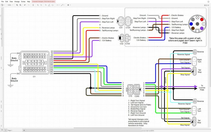
So, you're looking to understand the trailer wiring diagram for your Nissan Frontier? Excellent! Whether you're planning to install a trailer brake controller, diagnose faulty trailer lights, or simply want a better understanding of your truck's electrical system, knowing this diagram is crucial. This isn't just about plugging things in; it's about ensuring safety, proper functionality, and preventing potentially costly electrical damage. We're going to break down the diagram in a way that makes sense, even if you're not an electrical engineer.
Purpose of the Nissan Frontier Trailer Wiring Diagram
A trailer wiring diagram is essentially a roadmap of the electrical connections between your Nissan Frontier and a trailer. It illustrates how the truck's electrical system interfaces with the trailer's lighting and, if equipped, braking systems. Understanding this diagram is invaluable for:
- Repairs and Troubleshooting: Identifying and fixing wiring issues in either the truck or the trailer. For example, if your trailer's brake lights aren't working, the diagram will help you pinpoint the problem area.
- Installation of Accessories: Installing a trailer brake controller, auxiliary power sources, or other towing-related equipment.
- Customization: Modifying the wiring to suit specific needs, like adding extra lighting. However, be extremely cautious when modifying, as incorrect wiring can be dangerous.
- Preventive Maintenance: Visually inspecting wiring connections for corrosion or damage, ensuring everything is in good working order.
- General Knowledge: Developing a deeper understanding of your vehicle's electrical system, which can be helpful for various DIY repairs and modifications.
Key Specs and Main Parts
The Nissan Frontier, depending on the year and trim, typically uses a standard 7-way round (also known as a 7-pin RV blade connector) or a 4-way flat connector for trailer wiring. The 7-way connector is the more common and versatile option, providing connections for:
- Ground (White Wire): Provides a common ground for all electrical circuits. This is the backbone of the entire system.
- Tail Lights (Brown Wire): Powers the trailer's tail lights.
- Left Turn/Brake Light (Yellow Wire): Controls the left turn signal and brake light.
- Right Turn/Brake Light (Green Wire): Controls the right turn signal and brake light.
- Electric Brakes (Blue Wire): Activates the electric brakes on the trailer (requires a trailer brake controller in the truck). This is a high-current circuit and crucial for safe towing.
- Reverse Lights (Black Wire): Powers the trailer's reverse lights.
- Auxiliary Power (Red or Orange Wire): Provides a 12V power source for charging trailer batteries or powering interior lights (often always-on or ignition-switched depending on the Frontier model).
The 4-way connector, on the other hand, only supports the basic lighting functions:
- Ground (White Wire): Same as above.
- Tail Lights (Brown Wire): Same as above.
- Left Turn/Brake Light (Yellow Wire): Same as above.
- Right Turn/Brake Light (Green Wire): Same as above.
Important: The specific wire colors and pin locations can sometimes vary slightly depending on the Frontier's year and trim. Always refer to the wiring diagram specific to *your* vehicle.
Symbols and Conventions
Understanding the symbols used in the wiring diagram is essential. Here's a breakdown of common symbols:
- Solid Lines: Represent wires. The thicker the line, generally the higher the current carrying capacity.
- Dashed Lines: May indicate shielded wires or wires that are part of a harness.
- Circles: Represent connections or splices.
- Rectangles: Can represent components like relays, fuses, or the trailer connector itself. These are often labeled with their function (e.g., "Trailer Tail Light Relay").
- Arrows: Indicate the direction of current flow.
- Ground Symbol (Usually looks like three horizontal lines stacked on top of each other, decreasing in size): Indicates a ground connection to the vehicle's chassis.
- Color Codes: Wires are color-coded (e.g., BLU for blue, GRN for green, WHT for white). The diagram will have a key explaining the abbreviations.
The diagram will also show the location of fuses and relays related to the trailer wiring. Knowing where these are located is crucial for troubleshooting. Fuses are represented by a zigzag line within a rectangle and are labeled with their amperage rating (e.g., "20A"). Relays are typically represented by a coil symbol and a switch symbol, indicating their function as an electrically controlled switch.
How It Works
The trailer wiring system taps into the Frontier's existing electrical system. When you activate a lighting function (e.g., turn signal, brake light), the corresponding signal is sent from the truck's control module to the trailer connector. For example, when you press the brake pedal, the brake light signal travels from the brake light switch, through the truck's wiring harness, to the appropriate pin on the 7-way or 4-way connector, ultimately illuminating the trailer's brake lights.
The trailer brake controller (if installed) intercepts the brake signal and applies voltage to the blue wire, which controls the electric brakes on the trailer. The amount of voltage applied is typically proportional to the deceleration rate of the truck, providing smooth and controlled braking. A faulty brake controller or wiring in this circuit can lead to the trailer brakes locking up or failing to engage at all – a very dangerous situation.
The auxiliary power wire provides a constant or ignition-switched 12V power source to the trailer. This can be used to charge the trailer's battery while driving or to power interior lights and appliances when the trailer is connected to the truck.
Real-World Use: Basic Troubleshooting
Here are some basic troubleshooting tips using the trailer wiring diagram:
- No Lights on the Trailer: Start by checking the ground connection (white wire) on both the truck and trailer. Corrosion or a loose connection is a common culprit. Next, check the fuses related to the trailer lights in the truck's fuse box.
- One Light Not Working: Use a multimeter to check for voltage at the corresponding pin on the trailer connector when the light function is activated. If there's no voltage, trace the wiring back to the source (e.g., the turn signal switch or brake light switch) using the diagram.
- Trailer Brakes Not Working: Check the blue wire connection on both the truck and trailer. Verify that the trailer brake controller is properly installed and functioning. Use a multimeter to check for voltage on the blue wire when the brake pedal is pressed. Also check the condition of the trailer brake magnets if issues persists.
- Short Circuit: A blown fuse is a sign of a short circuit. Disconnect the trailer and replace the fuse. If the fuse blows again with the trailer disconnected, the short is in the truck's wiring. If it only blows when the trailer is connected, the short is in the trailer wiring.
Always use a test light or multimeter to verify voltage and continuity. Don't rely solely on visual inspection.
Safety Considerations
Working with automotive electrical systems can be dangerous. Here are some key safety points:
- Disconnect the Battery: Before working on any electrical wiring, disconnect the negative terminal of the truck's battery to prevent accidental shorts and electric shock.
- Use Appropriate Tools: Use insulated tools designed for automotive electrical work.
- Proper Wire Gauge: Use the correct gauge wire for the application. Undersized wire can overheat and cause a fire. The wiring diagram may specify the required wire gauge for certain circuits.
- Secure Connections: Ensure all wiring connections are secure and properly insulated. Use heat shrink tubing or electrical tape to protect exposed wires.
- Beware of Airbag Systems: Be extremely careful when working near airbag wiring. Accidental activation of an airbag can cause serious injury. Consult the service manual for airbag disabling procedures if necessary.
- High-Current Circuits: The electric brake circuit is a high-current circuit. Use heavy-gauge wire and high-quality connectors to ensure proper operation and prevent overheating.
Incorrect wiring can not only damage your truck's electrical system but also create a fire hazard. If you're not comfortable working with electrical wiring, it's best to consult a qualified mechanic.
You should also be aware of the potential of electrical shock when working with 12V circuits, especially when wet. Avoid working on your vehicle’s electrical system in wet conditions.
By following the safety precautions, you can ensure your safety and the safety of others while working with the trailer wiring system.
We have the Nissan Frontier trailer wiring diagram file available for download. This detailed diagram will provide the specific information you need for your truck's year and trim level.