
Nissan Frontier Trailer Wiring Harness
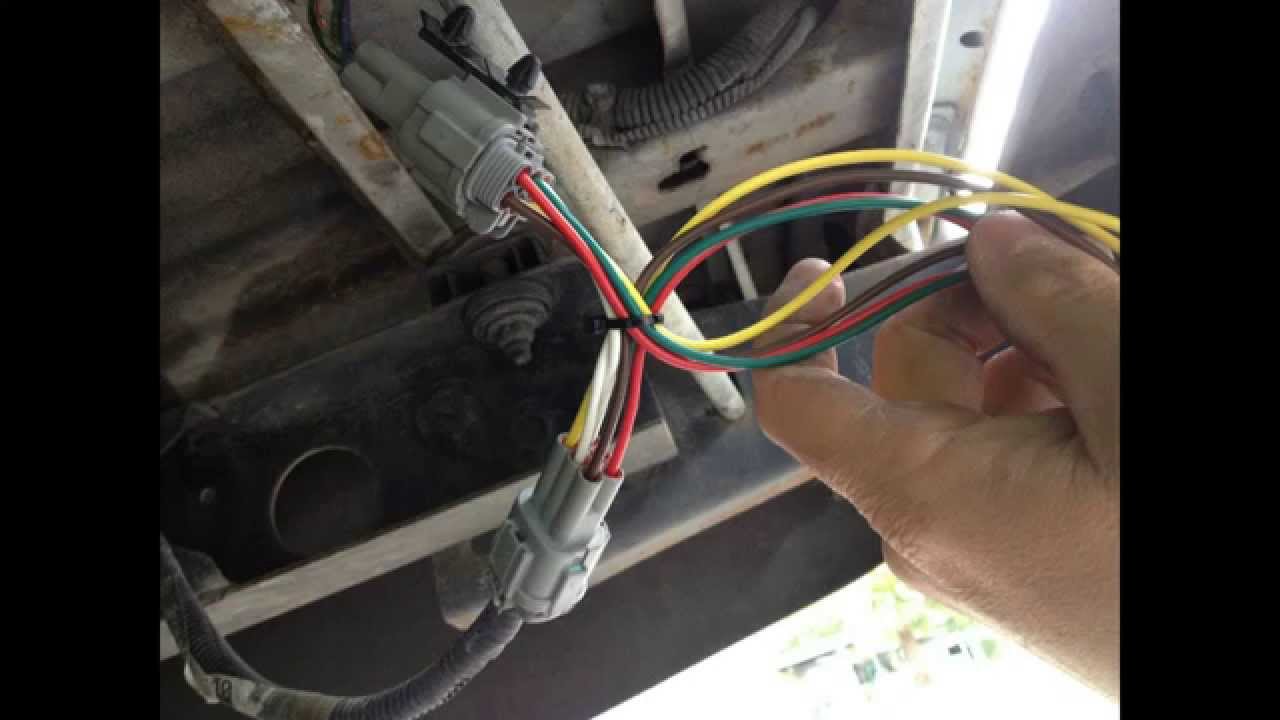
Understanding your Nissan Frontier's trailer wiring harness is crucial for safe towing, performing repairs, or even customizing your truck. Whether you're diagnosing a faulty brake light on your trailer or planning to install an aftermarket trailer brake controller, a solid grasp of the wiring is essential. This guide will break down the Frontier's trailer wiring harness, providing you with the knowledge to confidently tackle wiring-related tasks.
Purpose of the Wiring Diagram
The wiring diagram for your Nissan Frontier's trailer harness serves as a roadmap, showing the precise connections and functions of each wire within the system. Without it, troubleshooting becomes a guessing game, potentially leading to short circuits, damage to your vehicle's electrical system, or, most importantly, unsafe towing conditions. Specifically, this diagram matters for:
- Diagnostics and Repair: Pinpointing the cause of trailer light malfunctions (brake lights, turn signals, running lights).
- Installation of Aftermarket Components: Integrating trailer brake controllers, supplemental lighting, or auxiliary power connections.
- Customization: Rewiring or modifying the harness to meet specific towing needs.
- General Understanding: Comprehending how the trailer's electrical system interacts with your Frontier's electrical system.
Key Specs and Main Parts of the Trailer Wiring Harness
The Nissan Frontier typically uses a standard 7-way RV blade connector (also called a 7-pin connector) or a 4-way flat connector, depending on the factory option installed or aftermarket modifications. The 7-way connector is more common for trailers with electric brakes, while the 4-way is sufficient for trailers without brakes. Here's a breakdown of the common wires and their functions:
- Ground (White): Provides a return path for all electrical circuits. Critical for proper operation.
- Tail Lights/Running Lights (Brown): Powers the trailer's tail lights and side marker lights.
- Left Turn Signal/Brake Light (Yellow): Controls the left turn signal and brake light on the trailer.
- Right Turn Signal/Brake Light (Green): Controls the right turn signal and brake light on the trailer.
- Electric Brakes (Blue): Delivers power to the trailer's electric brakes. Requires a trailer brake controller in the Frontier.
- 12V Auxiliary Power (Black): Provides a constant 12V power source to the trailer, often used for charging a trailer battery or running interior lights. This wire is typically fused.
- Reverse Lights (Purple): Activates the trailer's reverse lights when the Frontier is in reverse (Less common on 4-way connectors).
Key Components:
- Trailer Connector: The physical interface between the Frontier and the trailer.
- Wiring Harness: The bundle of wires connecting the connector to the Frontier's electrical system.
- Fuses and Relays: Protect the electrical circuits from overloads and control high-current circuits.
- Trailer Brake Controller (if equipped): Regulates the power sent to the trailer's electric brakes.
Symbols and Conventions in a Wiring Diagram
Understanding the symbols used in the wiring diagram is paramount. Here's a brief overview:
- Solid Lines: Represent wires. Thicker lines often indicate wires carrying higher current.
- Dashed Lines: May indicate shielded wires or wires that are part of a specific harness segment.
- Colors: Wires are identified by color codes (e.g., BLK for black, WHT for white, BLU for blue). Standard color conventions are generally followed but always verify with the diagram.
- Circles with Numbers: Represent connector pins. The number inside the circle corresponds to the pin number on the connector.
- Ground Symbol: A triangle pointing downwards, indicating a connection to the vehicle's chassis ground.
- Fuse Symbol: A wavy line inside a rectangle, indicating a fuse. The fuse rating (amperage) is usually noted next to the symbol.
- Relay Symbol: A rectangle with a coil symbol inside, representing an electrical relay.
The diagram will also indicate the gauge (thickness) of each wire. Wire gauge is crucial – using a wire gauge that is too thin can lead to overheating and potential fire hazards.
How It Works: The Flow of Electricity
The trailer wiring harness allows your Frontier's electrical system to control the lights and brakes on the trailer. When you activate the turn signal, brake pedal, or headlights in your Frontier, the corresponding electrical signals are sent through the harness to the trailer. The harness then directs the current to the appropriate lights on the trailer, illuminating them accordingly.
The ground wire is essential for completing the electrical circuit. Without a good ground connection, the lights will not function correctly.
If your trailer has electric brakes, the trailer brake controller plays a vital role. When you press the brake pedal, the brake controller sends a variable amount of current to the trailer's brakes, proportional to the braking force. This helps to prevent the trailer from pushing against the tow vehicle during braking, providing a smoother and safer stopping experience.
Real-World Use: Basic Troubleshooting Tips
Here are some common problems and troubleshooting steps:
- No Lights on Trailer: Start by checking the ground connection. Then, check the fuses in both your Frontier and the trailer. Use a multimeter to check for voltage at the trailer connector pins when the corresponding lights are activated.
- One Light Not Working: Check the bulb first. If the bulb is good, trace the wiring from the bulb back to the connector, looking for loose connections or damaged wires. Use a multimeter to check for continuity in the wire.
- Electric Brakes Not Working: Verify that the trailer brake controller is properly configured and that the gain is set appropriately. Check the blue wire for voltage when the brake pedal is pressed. Inspect the brake magnets on the trailer for damage.
Common tools for troubleshooting:
- Multimeter: For measuring voltage, current, and resistance.
- Test Light: A simple tool for checking for voltage.
- Wire Strippers/Crimpers: For making clean and secure wire connections.
- Electrical Tape or Heat Shrink Tubing: For insulating wire connections.
Safety Considerations
Working with automotive electrical systems can be dangerous. Always disconnect the negative terminal of your Frontier's battery before working on the trailer wiring harness. This will prevent accidental short circuits and electrical shocks.
High-risk components:
- Battery Connections: Handle battery cables and terminals with care. Ensure proper polarity when reconnecting the battery.
- Fuses and Relays: Always replace fuses with the correct amperage rating. Using a fuse with a higher rating can overload the circuit and cause a fire.
- Trailer Brake Controller Wiring: Ensure that the trailer brake controller is wired correctly and that the gain is set appropriately. Improperly configured brake controllers can lead to brake lockup or inadequate braking performance.
When making wire connections, always use proper crimping tools and ensure that the connections are secure and insulated. Avoid using twist-on wire connectors (wire nuts) in automotive applications, as they are prone to loosening and corroding.
Always double-check your work before reconnecting the battery and testing the trailer lights. It’s better to be safe than sorry when dealing with electricity.
We have a detailed wiring diagram file available for download, which can be a great resource for your work. This file offers a comprehensive view of the wiring layout, making your tasks easier and more accurate.