
Nissan Mass Air Flow Sensor Wiring Diagram
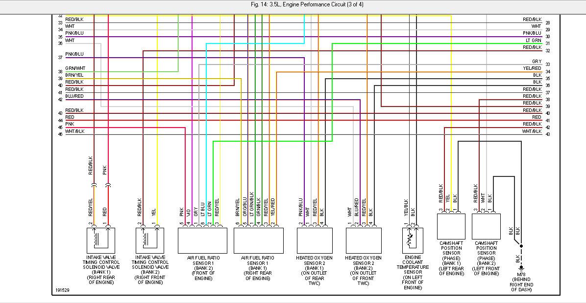
Understanding your Nissan's Mass Air Flow (MAF) sensor wiring diagram is crucial for several tasks, from basic maintenance and diagnostics to advanced engine tuning and modification. This article will provide a comprehensive breakdown of MAF sensor wiring diagrams, focusing on Nissan vehicles but with principles applicable across various makes and models. We'll explore the purpose of the diagram, key components, symbol interpretations, operational theory, real-world troubleshooting, and essential safety precautions. Think of this guide as your personalized workshop manual supplement, enabling you to confidently tackle MAF sensor-related issues.
Purpose of the MAF Sensor Wiring Diagram
The MAF sensor wiring diagram is more than just a collection of lines and symbols; it's a road map for understanding the electrical connections between the MAF sensor and the engine control unit (ECU). Its primary purposes include:
- Diagnostics: When your engine throws a code related to the MAF sensor (e.g., P0100, P0101, P0102), the wiring diagram helps you trace the circuit to identify potential breaks, shorts, or corrosion.
- Repairs: If a wire is damaged or a connector needs replacement, the diagram shows the correct wiring configuration, preventing misconnections that could damage the ECU.
- Performance Tuning/Modifications: When upgrading your engine or installing aftermarket components, the diagram ensures proper MAF sensor integration for optimal performance. This is especially important when dealing with larger MAF housings that require rescaling.
- Learning and Education: Even if you're not actively working on your car, studying the diagram deepens your understanding of engine management systems and electrical circuits.
Key Specs and Main Parts of a Nissan MAF Sensor Circuit
A typical Nissan MAF sensor circuit involves several essential components:
- MAF Sensor: The heart of the system, measuring the mass of air entering the engine. Common types include hot-wire and hot-film sensors.
- ECU (Engine Control Unit): The "brain" of the engine, receiving the MAF sensor's signal and adjusting fuel delivery and ignition timing accordingly.
- Wiring Harness: The bundle of wires connecting the MAF sensor to the ECU and other components.
- Connectors: Plugs that allow easy connection and disconnection of the MAF sensor. These are prone to corrosion and damage.
- Power Supply: The MAF sensor requires a stable voltage supply, typically 5V, provided by the ECU or a dedicated voltage regulator.
- Ground: A solid ground connection is crucial for accurate sensor readings.
- Signal Wire: Transmits the MAF sensor's output voltage or frequency signal to the ECU, representing the measured airflow.
Key Specifications:
- Voltage Range: Typically 0-5V DC for analog MAF sensors. Frequency range may vary for digital MAF sensors. Consult your vehicle's specific service manual for precise values.
- Pinout: The specific arrangement of wires in the connector, which varies depending on the vehicle model and year.
- Wire Gauge: The thickness of the wires, affecting their current-carrying capacity.
- Resistance Values: Checking the resistance of the MAF sensor's internal components can help diagnose faulty sensors.
Understanding Wiring Diagram Symbols
Wiring diagrams use standardized symbols to represent components and connections. Deciphering these symbols is essential for accurate interpretation.
- Lines: Represent wires. Solid lines typically indicate a direct connection, while dashed lines may represent shielded cables or less common connections. Line thickness may also indicate wire gauge.
- Colors: Wires are color-coded for easy identification. Common colors include Red (power), Black (ground), Green, Blue, Yellow, and White. Always refer to the color code legend specific to your vehicle.
- Connectors: Depicted as interlocking shapes or circles with numbers indicating pin positions.
- Ground Symbols: Various symbols represent different types of ground connections, such as chassis ground, engine ground, or signal ground.
- ECU Symbols: Usually represented as a box or rectangle with labeled pins and internal circuitry.
- Resistors: Zigzag lines represent resistors, with their resistance value often indicated nearby.
- Voltage Sources: A circle with a "+" sign indicates a positive voltage source.
Example: A solid red line connecting a "+" symbol to pin 1 of the MAF sensor connector indicates a 12V or 5V power supply wire. A black line connected to a ground symbol near the MAF sensor signifies a ground wire.
How the MAF Sensor Works
The MAF sensor measures the amount of air entering the engine, which is crucial for the ECU to calculate the correct fuel-to-air ratio. There are two main types of MAF sensors:
- Hot-Wire MAF Sensor: A heated wire is placed in the airflow. As air flows past the wire, it cools down. The ECU increases the current through the wire to maintain a constant temperature. The amount of current required is directly proportional to the airflow. This current is then converted to a voltage signal that the ECU reads.
- Hot-Film MAF Sensor: Similar to the hot-wire sensor, but uses a thin film element instead of a wire. This provides faster response times and greater accuracy.
The ECU uses the MAF sensor's signal to determine the engine's load and adjust fuel injection timing and duration accordingly. A faulty MAF sensor can lead to a variety of problems, including:
- Poor fuel economy
- Rough idling
- Stalling
- Loss of power
- Check engine light (CEL) illumination
Real-World Use: Basic Troubleshooting Tips
Here are some basic troubleshooting steps you can perform using the MAF sensor wiring diagram:
- Visual Inspection: Check the wiring harness and connector for any signs of damage, corrosion, or loose connections.
- Voltage Check: Use a multimeter to verify that the MAF sensor is receiving the correct voltage (typically 5V). Test between the power supply pin and ground.
- Ground Check: Ensure a solid ground connection by checking the resistance between the ground pin and the chassis. A good ground should have near-zero resistance.
- Signal Wire Check: With the engine running, measure the voltage on the signal wire. The voltage should vary with engine speed. A static voltage may indicate a faulty sensor or wiring problem.
- Continuity Test: With the ignition off and the MAF sensor disconnected, check the continuity of each wire between the MAF sensor connector and the ECU connector. This ensures there are no breaks in the wiring.
- Scan Tool Diagnostics: Use an OBD-II scan tool to read MAF sensor data and compare it to expected values. This can help identify sensor drift or inaccurate readings.
Example: If you suspect a broken wire, use a multimeter in continuity mode. Place one probe on the MAF sensor connector pin and the other probe on the corresponding ECU connector pin. If the multimeter doesn't beep or show continuity (typically near zero ohms), the wire is broken.
Safety Precautions
Working with automotive electrical systems involves inherent risks. Take these precautions:
- Disconnect the Battery: Always disconnect the negative battery terminal before working on any electrical components. This prevents accidental shorts and potential damage to the ECU.
- Use Proper Tools: Use insulated tools designed for automotive electrical work.
- Avoid Water: Never work on electrical components in wet conditions.
- Be Careful with Airbag Systems: Some wiring harnesses may run near airbag modules. Handle these harnesses with extreme care to avoid accidental airbag deployment.
- Proper Grounding: Ensure your work area and tools are properly grounded.
High-Risk Components: The ECU is particularly sensitive to voltage spikes and short circuits. Always double-check your wiring before reconnecting the battery. Damaging the ECU can be very costly.
We have the file containing a general wiring diagram and some Nissan specific wiring diagrams that you can use as reference. Please review the terms and conditions, then you can download the file from the link at the bottom of this page.