Nissan Rogue 2013 Fuse Box Diagram
The 2013 Nissan Rogue is a popular compact SUV, known for its reliability and practicality. However, like any vehicle, electrical issues can arise. Understanding the fuse box diagram for your Rogue is crucial for diagnosing and resolving these issues efficiently. This guide will provide an in-depth look at the 2013 Nissan Rogue's fuse box diagram, empowering you to perform basic electrical troubleshooting and repairs.
Purpose of Understanding the Fuse Box Diagram
The fuse box diagram is essentially a roadmap to your vehicle's electrical system. It serves several critical purposes:
- Troubleshooting: When an electrical component fails (e.g., a headlight, radio, or power window), the fuse box is the first place to check. The diagram helps you identify the correct fuse to inspect.
- Repairs: Replacing a blown fuse is a simple repair, but using the diagram ensures you replace it with the correct amperage fuse to prevent further damage.
- Modifications: If you're adding aftermarket electrical accessories (e.g., a new sound system or auxiliary lights), you need to understand the fuse box layout to tap into the electrical system safely.
- Learning Your Vehicle: Familiarizing yourself with the fuse box diagram provides a deeper understanding of your vehicle's electrical architecture.
Key Specs and Main Parts
The 2013 Nissan Rogue typically has two main fuse box locations:
- Interior Fuse Box: Located inside the cabin, usually under the dashboard on the driver's side or behind the glove compartment. This fuse box primarily houses fuses for interior components like the radio, lights, power windows, and climate control system.
- Engine Compartment Fuse Box: Located in the engine bay, often near the battery. This fuse box houses fuses and relays for critical engine components such as the fuel pump, ignition system, anti-lock braking system (ABS), and cooling fan.
Key components within each fuse box include:
- Fuses: These are the sacrificial components that protect the electrical circuits. They contain a thin wire that melts and breaks the circuit when an overload or short circuit occurs. Fuses are rated in amperes (amps or A), indicating the amount of current they can safely handle.
- Relays: These are electromechanical switches that control high-current circuits using a low-current signal. Relays are used to switch on/off components like the headlights, starter motor, and air conditioning compressor.
- Fuse Puller: A small plastic tool designed to safely remove fuses from the fuse box without damaging them or your fingers. Most fuse boxes have a fuse puller attached to the inside of the cover.
- Diagram Label: A sticker or insert inside the fuse box cover that shows the location and function of each fuse and relay. This is the most critical part!
Understanding Fuse Box Symbols
Fuse box diagrams use various symbols to represent different components and their functions. Here's a breakdown of common symbols:
- Fuses: Typically represented by a rectangular shape with a line or wavy line running through it. The amperage rating is usually printed next to the symbol (e.g., 10A, 15A, 20A). Different fuse types, like blade fuses, are shown using this general symbol.
- Relays: Usually represented by a square or rectangular shape with connecting lines indicating the coil and switch circuits.
- Lines: Solid lines represent the electrical circuits connecting the fuses and relays to the components they power. Thicker lines often indicate higher-current circuits.
- Colors: While not always standardized, fuse box diagrams may use colors to differentiate between different circuit types. For example, red might indicate a constant power supply, while blue might indicate an ignition-switched power supply. Refer to your specific diagram for the color code.
- Icons: Small icons are often used to represent the function of each fuse. These icons might depict a headlight, a radio, a window, or other components. Understanding these icons makes it easier to identify the correct fuse.
How It Works: The Electrical Circuit
To understand how fuses protect your car's electrical system, it's essential to grasp the basic concept of an electrical circuit.
An electrical circuit is a closed loop that allows electricity to flow from a power source (e.g., the battery) through a component (e.g., a headlight) and back to the power source. The fuse is placed in this circuit as a safety device. If there's a short circuit (where the electricity takes an unintended path with low resistance) or an overload (where too much current flows through the circuit), the current increases dramatically. This excessive current heats up the fuse wire, causing it to melt and break the circuit. This interrupts the flow of electricity and prevents damage to the wiring and the electrical component.
Real-World Use: Basic Troubleshooting Tips
Here's a step-by-step guide to troubleshooting electrical problems using the fuse box diagram:
- Identify the Problem: Determine which electrical component is not working.
- Locate the Fuse Box Diagram: Find the diagram inside the fuse box cover or in your owner's manual.
- Identify the Correct Fuse: Using the diagram, locate the fuse that corresponds to the non-working component.
- Inspect the Fuse: Use a fuse puller or needle-nose pliers (carefully!) to remove the fuse. Visually inspect the fuse. If the wire inside the fuse is broken or blackened, the fuse is blown.
- Test the Fuse (Optional): For a more accurate diagnosis, use a multimeter set to continuity mode. If the multimeter shows no continuity (no beep or zero resistance), the fuse is blown.
- Replace the Fuse: Replace the blown fuse with a new fuse of the same amperage rating. Using a fuse with a higher amperage rating can be dangerous and can cause further damage.
- Test the Component: Turn on the component to see if it's now working. If it's working, the problem is solved.
- Investigate Further: If the fuse blows again immediately after replacement, there is a short circuit or overload in the circuit. This requires further investigation and may need a professional mechanic.
Safety Considerations
Working with electrical systems can be dangerous. Keep the following safety precautions in mind:
- Disconnect the Battery: Before working on the electrical system, disconnect the negative (-) terminal of the battery to prevent accidental shorts.
- Use the Correct Fuse: Always replace a blown fuse with a fuse of the same amperage rating. Never use a fuse with a higher rating.
- Avoid Water: Never work on the electrical system in wet conditions.
- High-Current Components: Be extremely cautious when working with circuits that power high-current components like the starter motor, alternator, and ABS system. These circuits can carry significant current and pose a risk of electrical shock or burns. If you're not comfortable working with these circuits, consult a professional mechanic. Relays control these often, so be extra cautious when swapping relays as well.
By understanding the fuse box diagram and following these troubleshooting tips, you can confidently diagnose and resolve many common electrical issues in your 2013 Nissan Rogue. However, remember that complex electrical problems may require the expertise of a qualified mechanic.
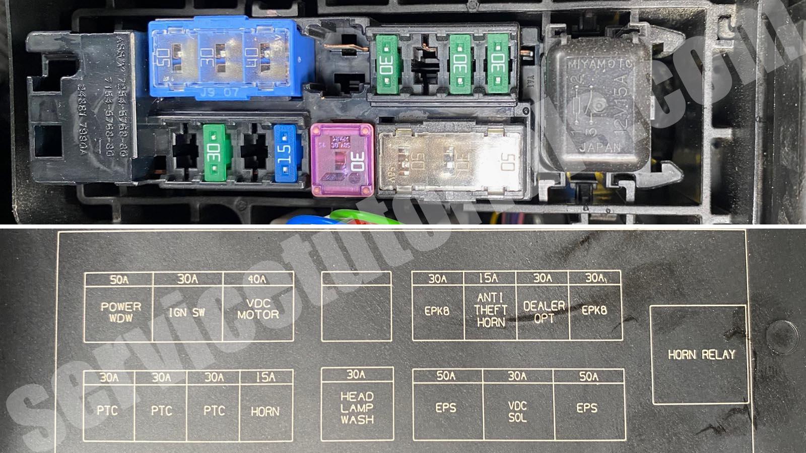
We have the 2013 Nissan Rogue fuse box diagram available for download. This diagram provides a detailed visual representation of the fuse and relay locations, along with their corresponding functions. This resource will be invaluable for your troubleshooting and repair efforts.