
Nissan Titan Tail Light Wiring Diagram
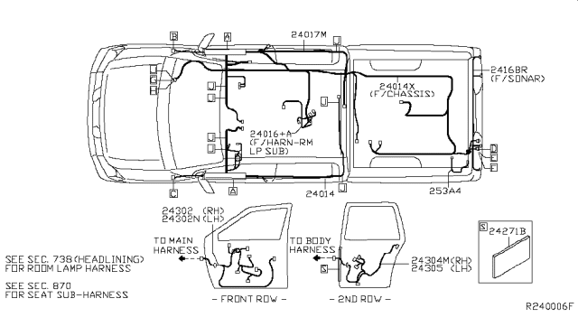
The tail light wiring diagram for your Nissan Titan is an invaluable resource, whether you're performing routine maintenance, tackling a complex repair, or planning a custom modification. Understanding this diagram allows you to diagnose electrical issues, replace faulty components, and even add aftermarket accessories with confidence. Without it, you're essentially navigating your truck's electrical system blind.
Purpose of the Nissan Titan Tail Light Wiring Diagram
This diagram acts as a roadmap to the Titan's tail light electrical system. It serves several crucial purposes:
- Troubleshooting: Pinpointing the source of electrical problems, such as a malfunctioning brake light or turn signal.
- Repair: Identifying and replacing damaged wires, connectors, or bulbs correctly.
- Modification: Safely adding accessories like auxiliary lights or aftermarket tail light assemblies.
- Understanding: Gaining a deeper understanding of how the tail light system integrates with the vehicle's overall electrical architecture.
Key Specs and Main Parts
Before diving into the specifics, let's outline the core components of the Nissan Titan's tail light system and their associated specifications. Note that specific wiring configurations can vary slightly depending on the model year, trim level (e.g., XE, SE, LE, PRO-4X, Platinum Reserve), and whether the truck has standard or LED tail lights. This article assumes a standard halogen tail light setup, but the principles remain the same.
Main Components:
- Tail Light Assembly: Contains the various bulbs (or LEDs) for tail lights, brake lights, turn signals, and reverse lights.
- Bulbs/LEDs: Individual light sources responsible for illumination. Common bulb types include incandescent bulbs (often 3157 or similar dual-filament bulbs) or LED modules.
- Wiring Harness: A bundle of wires that connects the tail light assembly to the vehicle's electrical system.
- Connectors: Plugs that allow for easy connection and disconnection of the wiring harness to the tail light assembly and the main vehicle wiring.
- Fuses: Protective devices that prevent overcurrent from damaging the electrical system. Tail lights typically have their own dedicated fuse(s) located in the fuse box.
- Relays (Optional): Some circuits, especially those involving trailer wiring, may utilize relays to switch higher current loads.
- Grounding Points: Connection points where the electrical circuit completes its path back to the vehicle's chassis. Proper grounding is essential for reliable operation.
Typical Wire Colors (Subject to Change – Always Refer to the Diagram):
While Nissan uses standardized colors, always verify with the specific wiring diagram for your model year. General guidelines:
- Ground: Black (BLK)
- Tail Lights: Green (GRN) or Brown (BRN)
- Brake Lights: Red (RED) or Green/White (GRN/WHT)
- Left Turn Signal: Green/Yellow (GRN/YEL)
- Right Turn Signal: Green/Black (GRN/BLK)
- Reverse Lights: Pink (PNK) or White/Black (WHT/BLK)
Understanding Wiring Diagram Symbols
Wiring diagrams use standardized symbols to represent electrical components and connections. Understanding these symbols is crucial for interpreting the diagram correctly.
- Solid Lines: Represent wires. The thickness may indicate wire gauge (thicker lines = larger gauge).
- Dashed Lines: Often indicate wires that are part of a separate circuit or a ground connection. Sometimes used to distinguish between different wire gauges.
- Circles: May represent bulbs or other small electrical components.
- Rectangles: Often represent relays or electronic control modules (ECMs).
- Ground Symbol: A series of descending horizontal lines indicating a connection to the vehicle's chassis ground.
- Connector Symbol: A combination of squares or circles representing a multi-pin connector. Numbered pins may be indicated.
- Fuse Symbol: A wavy line inside a rectangle, indicating a fuse. The amperage rating (e.g., 10A, 15A) is usually specified.
- Switches: Represented by a line that either connects or disconnects two points, indicating an open or closed circuit.
- Color Codes: Letter abbreviations indicating wire color (e.g., BLK = Black, RED = Red, GRN = Green, WHT = White, YEL = Yellow, BLU = Blue).
The diagram will also show how these components are interconnected, allowing you to trace the flow of electricity through the circuit.
How It Works: The Basic Electrical Flow
The tail light circuit is relatively simple in concept. When the headlights are switched on, power flows from the battery, through the headlight switch, to the tail light relay (if equipped) or directly to the tail light circuit. The tail lights illuminate, providing visibility from the rear. Separate circuits control the brake lights, turn signals, and reverse lights.
- Tail Lights: Activated by the headlight switch, providing constant illumination when driving at night.
- Brake Lights: Activated by the brake pedal switch. When the brake pedal is pressed, power flows to the brake light bulbs, signaling the driver is braking.
- Turn Signals: Activated by the turn signal stalk. When activated, power flows to the appropriate turn signal bulb (left or right) in a flashing pattern, controlled by the flasher relay (or integrated into the BCM - Body Control Module).
- Reverse Lights: Activated by the transmission when the vehicle is shifted into reverse. This sends power to the reverse light bulbs, providing illumination behind the vehicle.
Each circuit has its own wiring path, fuse, and ground connection. A fault in any of these components can cause the corresponding light to malfunction.
Real-World Use: Basic Troubleshooting Tips
Here are some basic troubleshooting steps you can take, using the wiring diagram as your guide:
- Start with the Obvious: Check the bulbs! A burned-out bulb is the most common cause of tail light problems.
- Check the Fuses: Use a test light or multimeter to check the tail light fuses in the fuse box. A blown fuse indicates a short circuit or overload in the corresponding circuit. Refer to the wiring diagram to identify the correct fuse.
- Inspect the Wiring Harness: Look for any signs of damage, such as frayed wires, corroded connectors, or loose connections. Pay close attention to areas where the harness is exposed to the elements or subject to vibration.
- Test the Ground Connection: Ensure the ground connection is clean and secure. A poor ground connection can cause intermittent or erratic behavior. Use a multimeter to test for continuity between the ground point and the vehicle's chassis.
- Use a Multimeter: Use a multimeter to check for voltage at the bulb socket and at various points along the wiring harness. If you're not getting voltage, trace the circuit back to the source (e.g., fuse, switch, relay) to identify the problem.
- Consult the Wiring Diagram: This is critical. Use the diagram to trace the circuit and identify potential points of failure. The diagram will show you the wire colors, connector locations, and component locations, making it easier to diagnose the problem.
Example: If the left turn signal is not working, use the wiring diagram to identify the left turn signal wire color and trace it back to the flasher relay or BCM. Check for voltage at the bulb socket and at the flasher relay. If there's no voltage at the bulb socket but voltage at the relay, there's a break in the wire between the relay and the bulb.
Safety Precautions
Working with automotive electrical systems can be dangerous. Always take the following precautions:
- Disconnect the Battery: Disconnect the negative battery terminal before working on any electrical components. This will prevent accidental shocks or short circuits.
- Work in a Well-Ventilated Area: Some electrical components may contain hazardous materials. Work in a well-ventilated area to avoid inhaling fumes.
- Use Proper Tools: Use insulated tools and wear appropriate safety gear, such as gloves and eye protection.
- Be Careful with Airbags: Avoid disturbing airbag wiring. Airbags can deploy unexpectedly, causing serious injury.
- High-Intensity Bulbs and LEDs: Some aftermarket tail lights use high-intensity bulbs or LEDs that can generate significant heat. Allow these components to cool down before handling them.
- Capacitors in LED circuits: Some circuits have capacitors that hold a charge even when the battery is disconnected. Discharge capacitors before touching the circuit.
Especially be cautious when working with circuits related to the brake lights and ABS (Anti-lock Braking System). A short circuit in these systems could have serious consequences.
By following these safety precautions and using the wiring diagram as your guide, you can safely and effectively troubleshoot and repair your Nissan Titan's tail light system.
We have the Nissan Titan Tail Light Wiring Diagram file available for download. This diagram will be invaluable in performing diagnostics and repairs on your vehicle.