
Nissan Wiring Diagram Color Codes Pdf
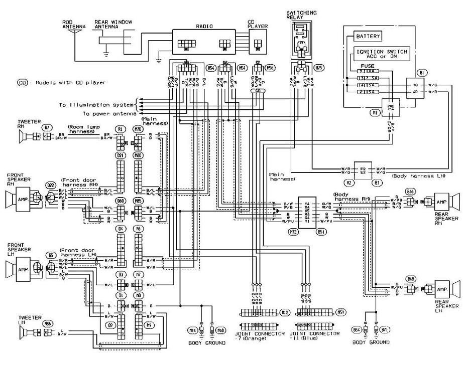
Alright, let's dive into Nissan wiring diagrams and their color codes. For those of you tackling your own car repairs, modifications, or just trying to understand your Nissan's electrical system better, these diagrams are indispensable. Think of them as the Rosetta Stone of your car's electrical heart. Without them, you're essentially poking around in the dark, hoping not to accidentally short something or miswire a component. We've got a downloadable PDF diagram available, which we'll mention again later. For now, let's understand how to use it.
Purpose of a Nissan Wiring Diagram
Why are wiring diagrams so important? Several reasons:
- Troubleshooting Electrical Issues: Imagine your headlights suddenly quit working. A wiring diagram helps you trace the circuit from the battery, through the fuse, switch, relay (if equipped), and finally to the headlights. You can identify potential breaks in the circuit, shorts to ground, or faulty components.
- Installing Aftermarket Accessories: Want to install a new stereo, alarm system, or auxiliary lights? A wiring diagram tells you exactly which wires to tap into, minimizing the risk of damaging the vehicle's existing electrical system.
- Performing Repairs: When replacing damaged wiring or components, a diagram ensures you reconnect everything correctly, maintaining the vehicle's functionality and safety.
- Understanding Vehicle Systems: Even if you're not actively repairing something, studying a wiring diagram provides a deeper understanding of how different systems interact, from the engine management to the anti-lock braking system (ABS).
Key Specs and Main Parts of a Wiring Diagram
A Nissan wiring diagram is a schematic representation of the vehicle's electrical circuits. It illustrates the connections, components, and wiring using symbols and color codes. Here's what you'll typically find:
- Components: These are the actual electrical parts, such as sensors, actuators, switches, relays, fuses, and the ECU (Engine Control Unit – the car's computer). Each component is represented by a specific symbol.
- Wiring: Solid lines represent wires. The thickness of the line usually doesn't represent wire gauge, but just visual clarity.
- Connectors: Represented by circles or other shapes, connectors show where wires join together. They're crucial for finding physical connection points in the vehicle.
- Ground Points: These indicate where circuits are grounded to the vehicle's chassis, providing a return path for the electrical current. Often represented by a triangle pointing downwards or a series of horizontal lines decreasing in length.
- Fuses and Circuit Breakers: Protection devices for overcurrents. Symbols vary, but they're generally easy to identify.
- Relays: Electrically operated switches. They're used to control high-current circuits with a low-current signal. The diagram will show both the relay coil and the switch contacts.
- Splice Points: Locations where multiple wires are joined together in the wiring harness.
Symbols, Lines, and Color Codes
Understanding the symbols and color codes is crucial for interpreting the diagram. The symbols used can vary slightly depending on the year and model of your Nissan, but some common examples include:
- Resistor: A zig-zag line.
- Capacitor: Two parallel lines.
- Inductor: A coiled line.
- Diode: A triangle pointing to a vertical line.
- Transistor: A more complex symbol depending on the type (NPN or PNP).
- Switch: A line that can be open or closed to complete or break a circuit. Several variations exist depending on the switch type (SPST, SPDT, etc.).
Wire Color Codes: This is where the real magic happens. Each wire in your Nissan's electrical system has a color code, and the wiring diagram uses these same codes to identify each wire. Common color abbreviations include:
- B: Black
- W: White
- R: Red
- G: Green
- L: Blue
- Y: Yellow
- Br: Brown
- Or: Orange
- P: Pink
- V: Violet (Purple)
- Gr: Gray
Often, you'll see a combination of two colors, such as "L/W" which means Blue with a White stripe. The first letter indicates the base color, and the second letter indicates the stripe color.
Lines: Solid lines represent wires. Dashed lines might represent shielding or grounds, depending on the diagram.
How It Works: Tracing a Circuit
Let's say you want to troubleshoot a non-functioning turn signal. Here's how you'd use a wiring diagram:
- Identify the Circuit: Locate the turn signal circuit on the diagram. It will show the battery, fuse, flasher relay (if equipped), turn signal switch, and the turn signal bulbs themselves.
- Start at the Power Source: Begin at the battery and follow the wire through the fuse. Check the fuse with a multimeter to confirm it's not blown.
- Trace the Wiring: Follow the wire to the turn signal switch. Use the color codes to identify the correct wire in the wiring harness.
- Check the Switch: Use a multimeter to check if the switch is functioning correctly. Does it make a connection when turned to the left or right?
- Follow the Wiring to the Bulbs: If the switch is working, follow the wiring from the switch to the turn signal bulbs. Check the bulbs themselves to see if they're burned out.
- Check the Ground: A faulty ground can also cause the turn signals to not work. Locate the ground point for the turn signal circuit and make sure it's clean and securely connected to the chassis.
Real-World Use: Basic Troubleshooting Tips
Here are some practical troubleshooting tips using wiring diagrams:
- Always start with the basics: Check the battery voltage, fuses, and ground connections first. These are the most common causes of electrical problems.
- Use a multimeter: A multimeter is your best friend for testing circuits. Learn how to use it to check voltage, continuity, and resistance. Continuity is particularly useful for checking if a wire is broken somewhere along its length.
- Isolate the Problem: Try to isolate the problem to a specific circuit or component. This will make troubleshooting much easier.
- Look for common ground points: Many electrical components share the same ground point. If several components are not working, suspect a faulty ground.
- Refer to the Wiring Diagram Constantly: Don't guess! Use the diagram to guide your troubleshooting.
Safety First!
Working with automotive electrical systems can be dangerous. Here are some safety precautions:
- Disconnect the Battery: Before working on any electrical system, disconnect the negative battery terminal. This will prevent accidental shorts and shocks.
- Be Careful with Airbags and SRS Systems: These systems contain explosive components. Consult the service manual before working near them. Improper handling can result in serious injury or death.
- Wear Safety Glasses: Protect your eyes from sparks and debris.
- Use Proper Tools: Use insulated tools to prevent electrical shocks.
- Don't Work Alone: It's always a good idea to have someone nearby in case of an emergency.
- Identify risky components: High-voltage components such as the ignition coil and fuel injectors carry a significant electrical charge. Handle with extreme caution, even with the battery disconnected, capacitors can store dangerous voltages. Let the vehicle sit disconnected for a while to allow them to discharge if possible.
We understand the importance of having access to the specific diagram for your vehicle. We have a Nissan Wiring Diagram Color Codes PDF available for download. While we can't guarantee it covers *every* Nissan model ever made, it's a great resource for most common vehicles. Search online with your year and model to find the exact diagram you need!