
One Wire Alternator Wiring Diagram Ford
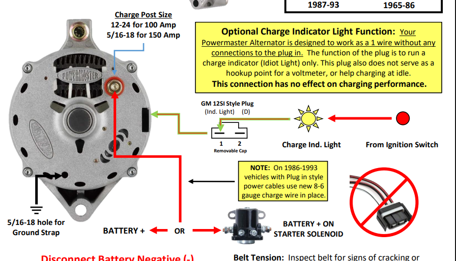
One-wire alternator conversions for Ford vehicles are a popular modification, often seen during engine swaps, restorations, or when simplifying wiring systems. This article dives into the wiring diagram for a one-wire alternator on a Ford, offering a detailed explanation suitable for experienced DIYers and modders.
Purpose of Understanding the One-Wire Alternator Wiring Diagram
Understanding this diagram is crucial for several reasons:
- Troubleshooting Charging Issues: When your battery isn't charging properly, a solid understanding of the one-wire system allows you to diagnose the problem effectively.
- Performing Conversions: If you're converting from a traditional multi-wire alternator to a one-wire setup, this diagram provides the roadmap for a successful installation.
- Custom Wiring: For those building custom harnesses or modifying existing wiring, the diagram ensures proper connections and prevents electrical problems.
- Educational Purposes: Expanding your knowledge of automotive electrical systems empowers you to tackle more complex repairs and modifications.
Key Specs and Main Parts of a One-Wire Alternator System
The simplicity of a one-wire alternator belies its functionality. Here are the key components:
- One-Wire Alternator: This is the heart of the system. Unlike traditional alternators with multiple connections, it only requires a single, heavy-gauge wire. Internally, it has a self-exciting voltage regulator.
- Heavy-Gauge Charging Wire: Typically 8-gauge or 4-gauge (depending on the alternator's amperage output), this wire carries the charging current from the alternator to the battery.
- Battery: The battery stores electrical energy and provides power to start the engine and run accessories.
- Battery Terminals: Where the charging wire connects to the battery.
- Fuse (Optional but Recommended): A high-amperage fuse placed close to the battery protects the system from overloads and shorts. Choose a fuse rating slightly higher than the alternator's maximum output.
- Ground Wire: A heavy-gauge wire that grounds the alternator to the vehicle's chassis, and another ground from the engine block to the chassis. Proper grounding is critical for reliable operation.
Symbols and Conventions in the Wiring Diagram
A wiring diagram is a symbolic representation of an electrical circuit. Understanding the symbols is key to interpreting the diagram:
- Solid Lines: Represent wires. The thicker the line, typically the larger the wire gauge.
- Dashed Lines: May represent ground connections or wires that are less critical.
- Circles: Often represent connections or junctions.
- Rectangles: Can represent various components like the voltage regulator.
- Alternator Symbol: A stylized "ALT" or a diagram resembling an alternator signifies the component.
- Battery Symbol: A series of short and long lines indicates a battery. The long line is the positive (+) terminal, and the short line is the negative (-) terminal.
- Fuse Symbol: A squiggly line enclosed in a rectangle, or a simple rectangle with a line through it, represents a fuse.
- Color Coding: Wires are often color-coded (e.g., Red for positive, Black for ground). The diagram should include a color key.
How a One-Wire Alternator System Works
The operation of a one-wire alternator system is straightforward:
- Starting the Engine: When the engine starts, the alternator begins to spin.
- Self-Excitation: At a certain RPM (usually around 1200-1500 RPM initially), the alternator's internal voltage regulator "excites" the alternator. This means it provides a small initial current to the field windings.
- Charging: Once excited, the alternator begins to generate a charging current.
- Voltage Regulation: The internal voltage regulator monitors the voltage and adjusts the alternator's output to maintain a consistent charging voltage, typically around 13.8-14.4 volts. This prevents overcharging the battery.
- Power Delivery: The charging current flows from the alternator, through the heavy-gauge charging wire, to the battery, replenishing its charge.
- Grounding: The alternator is grounded to the vehicle's chassis to complete the electrical circuit. A good, clean ground connection is vital.
The simplicity lies in the single wire handling the charging function. The alternator automatically regulates its output without needing external voltage sensing wires.
Real-World Use: Troubleshooting Tips
Here are some common issues and troubleshooting steps for a one-wire alternator system:
- Battery Not Charging:
- Check the Charging Wire: Ensure the heavy-gauge charging wire is securely connected to both the alternator and the battery. Inspect for corrosion or damage.
- Check the Ground Connection: Verify that the alternator is properly grounded to the chassis. Clean and tighten the ground connection. Also check the engine to chassis ground.
- Test the Alternator: Use a voltmeter to measure the alternator's output voltage while the engine is running. It should be between 13.8 and 14.4 volts. If it's significantly lower, the alternator may be faulty.
- Check the Fuse (if installed): Make sure the fuse hasn't blown.
- Alternator Overcharging:
- Check the Voltage Regulator: If the alternator is consistently outputting a voltage higher than 14.4 volts, the internal voltage regulator is likely faulty, and the alternator needs replacement.
- Alternator Not Exciting:
- Increase Engine RPM: Sometimes, the alternator needs a higher initial RPM to excite. Try revving the engine slightly to see if it starts charging.
- Check Internal Regulator: If the alternator never excites, even at higher RPMs, the internal regulator is likely faulty.
Important: When troubleshooting, always disconnect the negative battery cable before working on the electrical system to prevent shorts and potential damage.
Safety Considerations
Working with automotive electrical systems involves potential hazards. Here are some safety precautions:
- Disconnect the Battery: Always disconnect the negative battery cable before working on the electrical system.
- Wear Safety Glasses: Protect your eyes from sparks and debris.
- Use Insulated Tools: Use tools with insulated handles to prevent electrical shock.
- Be Cautious Around the Battery: Batteries contain sulfuric acid and can release explosive gases. Avoid sparks or open flames near the battery.
- Proper Wire Gauge: Always use the correct wire gauge for the application. Undersized wires can overheat and cause a fire. The heavy gauge wire is to handle the amperage of the alternator.
- Fuse Protection: Always use a fuse in the charging wire to protect the system from overloads and shorts.
The alternator's output is high amperage and can cause serious burns or electrical shock. Always exercise caution when working with the charging system.
The battery stores considerable energy, and short circuits can cause dangerous sparks and potential explosions.
By understanding the wiring diagram and following safe practices, you can confidently troubleshoot and maintain your one-wire alternator system on your Ford vehicle.
We have a detailed one-wire alternator wiring diagram file available for download. Please contact us for access to the file.