Owner Manual 1998 Ford F150 Fuse Box Diagram
Alright, let's dive into the 1998 Ford F-150 fuse box diagram. Whether you're tackling a wiring issue, installing aftermarket accessories, or simply trying to understand your truck a bit better, this diagram is your essential roadmap. We're not just talking about knowing where the fuses *are*, but truly understanding what each one protects and how the whole system is laid out. Think of it as a treasure map for your electrical system – find the right spot, and you'll unearth the solution to your problem.
Why You Need This Diagram
The purpose of a fuse box diagram goes far beyond just replacing a blown fuse. Sure, that's the most common use case. But with a good diagram, you can:
- Diagnose Electrical Issues: Is your radio dead? Headlights not working? A fuse box diagram helps you pinpoint the circuit responsible and check for blown fuses or other problems.
- Install Aftermarket Accessories: Adding a new sound system, auxiliary lights, or a trailer brake controller? You'll need to tap into the electrical system, and the fuse box is a convenient place to do it. The diagram ensures you're tapping into the correct circuit and using appropriate fuses.
- Understand Your Truck's Electrical System: Even if everything's working perfectly, studying the diagram provides valuable insight into how your F-150's electrical system is wired. This knowledge can be invaluable down the road when troubleshooting complex issues.
- Prevent Damage: Using the wrong fuse or overloading a circuit can lead to serious damage, even a fire. The diagram helps you avoid these mistakes.
Key Specs and Main Parts
The 1998 F-150 typically has two main fuse boxes:
- The Interior Fuse Box: Located under the dash, usually on the driver's side. This box contains fuses and relays for interior components like the radio, lights, power windows, and instrument panel.
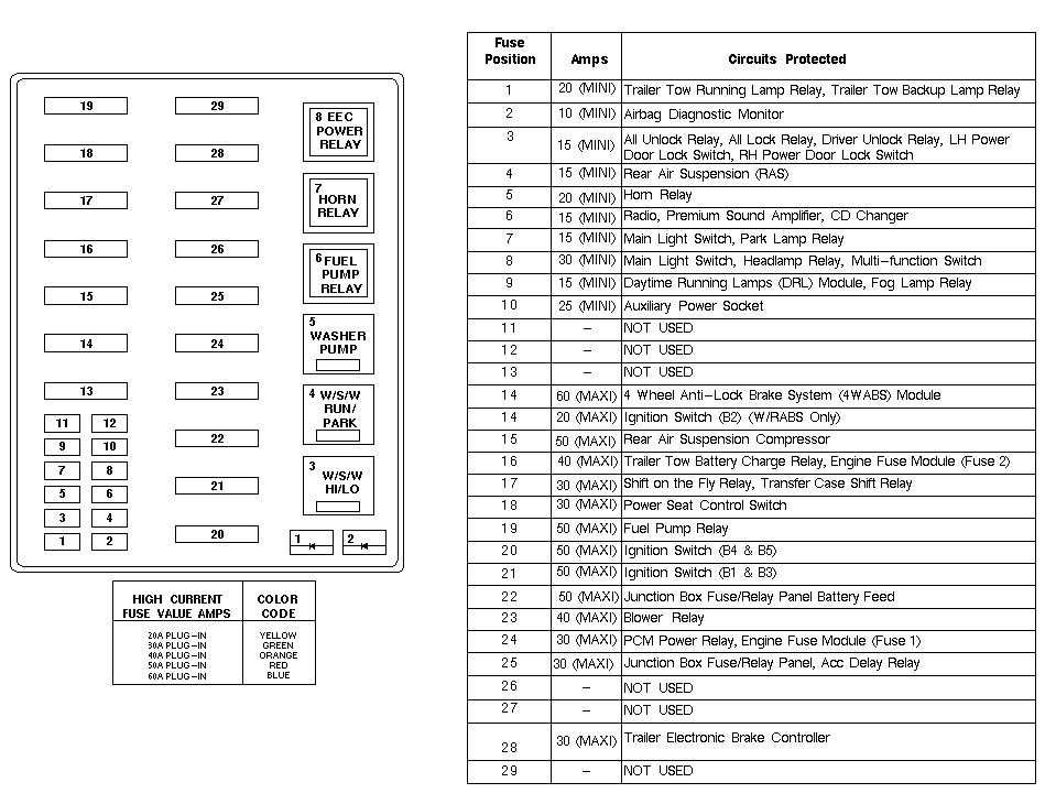
- The Engine Compartment Fuse Box (Power Distribution Box): Found under the hood, near the engine. This box houses fuses and relays for critical engine and drivetrain components, such as the fuel pump, ignition system, headlights, and starter.
When looking at the diagram, pay close attention to the following:
- Fuse Numbers: Each fuse has a unique number, usually printed on the fuse box itself and labeled on the diagram. This is your primary identifier.
- Fuse Amperage: This indicates the current (measured in amps) that the fuse can handle before blowing. Using a fuse with a higher amperage than specified is extremely dangerous, as it can allow excessive current to flow and damage components or start a fire. Always use the correct amperage!
- Circuit Description: The diagram will briefly describe what each fuse protects. For example, "Radio," "Headlights," or "Fuel Pump Relay."
- Relays: Relays are electromechanical switches that control high-current circuits using a low-current signal. The diagram will show the location of relays and their function.
Decoding the Symbols
Understanding the symbols on the fuse box diagram is crucial. Here's a breakdown of common elements:
- Lines: Solid lines represent electrical wires. Dashed lines may indicate ground connections or connections to other modules.
- Colors: Wire colors are often indicated on the diagram (e.g., "RD/WH" for red with a white stripe). This helps you trace wires in the vehicle.
- Fuse Symbol: A small rectangle or square with a wavy line inside typically represents a fuse.
- Relay Symbol: Relays are often depicted as a square or rectangle with coils and switch contacts.
- Ground Symbol: Looks like an upside-down Christmas tree or a series of decreasing horizontal lines.
Beyond these basics, you might encounter symbols for diodes, resistors, capacitors, and other electronic components. If you're unfamiliar with these, it's worth doing some research to understand their function in the circuit.
How It Works: The Electrical Circuit
To truly grasp the fuse box diagram, you need a basic understanding of how an electrical circuit works. Electricity flows from the battery (positive terminal) through a circuit, powering various components, and then returns to the battery (negative terminal, or ground). A fuse is a sacrificial component placed in this circuit. It's designed to break the circuit if the current exceeds a certain level, protecting the other components from damage.
When a fault occurs (e.g., a short circuit, where a wire accidentally touches ground), the current spikes. This high current heats up the fuse's internal element, causing it to melt and break the circuit. This prevents further damage to the wiring and components downstream.
The fuse box diagram shows you exactly where each fuse is located within these circuits and what components it protects. By tracing the circuit on the diagram, you can understand the flow of electricity and identify potential problem areas.
Real-World Use: Basic Troubleshooting
Let's say your interior lights aren't working. Here's how you can use the fuse box diagram to troubleshoot:
- Locate the Interior Fuse Box: It's usually under the dash on the driver's side.
- Consult the Diagram: Find the fuse labeled "Interior Lights" or something similar. The diagram will tell you the fuse number and amperage.
- Inspect the Fuse: Visually check the fuse. If the small wire inside is broken or blackened, the fuse is blown.
- Test the Fuse: For a more definitive test, use a multimeter set to continuity mode. Touch the probes to each end of the fuse. If the meter shows continuity (usually a beep or a reading close to zero ohms), the fuse is good. If there's no continuity, the fuse is blown.
- Replace the Fuse: Replace the blown fuse with a new one of the exact same amperage.
- Test the Circuit: Turn on the interior lights. If they work, you've solved the problem. If the new fuse blows immediately, there's a short circuit or other issue in the circuit that needs further investigation.
If a new fuse blows immediately, do not keep replacing the fuse with a higher amperage one. This is a recipe for electrical fire. Further diagnostics are needed to locate the short. Start by inspecting the wiring and connections related to the circuit you're working on. Look for frayed wires, damaged connectors, or signs of corrosion.
Safety First
Working with electrical systems can be dangerous. Here are some key safety precautions:
- Disconnect the Battery: Before working on any electrical components, disconnect the negative battery cable. This prevents accidental short circuits and electrical shocks.
- Use Proper Tools: Use insulated tools designed for electrical work.
- Never Bypass a Fuse: Bypassing a fuse with a wire or other conductive material is extremely dangerous and can lead to serious damage or fire.
- Be Careful Around High-Voltage Components: Components like the ignition coil and certain sensors can carry high voltage even with the battery disconnected. Use caution when working near these components.
- When in doubt, consult a professional: If you're not comfortable working with electrical systems, take your truck to a qualified mechanic.
Specifically, the fuel pump circuit can be risky, especially if you've recently been working on the fuel system. Any sparks near fuel vapors could be catastrophic. Always disconnect the battery and ensure the area is well-ventilated before working on fuel-related electrical components.
Understanding the 1998 Ford F-150 fuse box diagram is a valuable skill for any DIY mechanic. It empowers you to diagnose and repair electrical issues, install aftermarket accessories, and gain a deeper understanding of your truck's electrical system. Remember to always prioritize safety and consult a professional if you're unsure about anything. We have the file and you can download the diagram for your reference, and keep it handy for any future troubleshooting or modifications.