Owner Manual 2001 Ford Expedition Fuse Box Diagram
The 2001 Ford Expedition is a workhorse, known for its reliability and spaciousness. However, like any vehicle, electrical issues can arise. And when they do, navigating the labyrinth of wires can feel daunting. That's where a clear, accurate fuse box diagram becomes your best friend. We're going to delve deep into the specifics of the 2001 Ford Expedition fuse box diagram, providing you with the knowledge to troubleshoot electrical problems, perform modifications, and understand your vehicle's electrical system like a pro. Consider this your comprehensive guide.
Purpose of the 2001 Ford Expedition Fuse Box Diagram
Why bother with a fuse box diagram? The answer is simple: it's your roadmap to understanding and resolving electrical issues. Here's a breakdown of its key benefits:
- Troubleshooting: Identifying a blown fuse is the first step in fixing many electrical problems. The diagram pinpoints the exact fuse responsible for a specific circuit, saving you hours of guesswork.
- Repairs: Whether you're replacing a faulty component or repairing a wiring issue, the diagram helps you trace the circuit and understand the electrical flow.
- Modifications: Adding aftermarket accessories like lights, stereos, or alarm systems requires tapping into the vehicle's electrical system. The diagram allows you to do this safely and correctly, ensuring proper fuse protection for your new components.
- Learning: Studying the diagram helps you understand the overall architecture of your vehicle's electrical system. It's a valuable tool for anyone interested in automotive technology.
Key Specs and Main Parts of the Fuse Box
The 2001 Ford Expedition actually has multiple fuse boxes. Understanding their locations and functions is crucial.
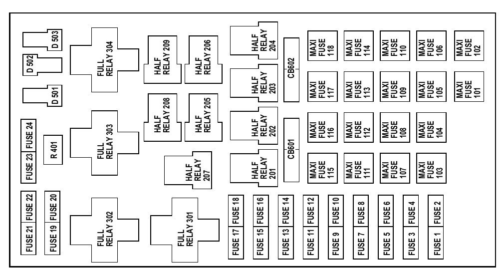
Main Fuse Box (Engine Compartment)
Located under the hood, typically on the driver's side, this fuse box houses the main fuses and relays that protect the engine, transmission, and other critical systems. This is often called the Power Distribution Box (PDB). It contains high-amperage fuses, often cartridge-style or Maxi-fuses, that handle significant electrical loads.
Secondary Fuse Box (Passenger Compartment)
Usually found under the dashboard on the driver's side, this fuse box protects circuits related to the interior components, such as lights, radio, windows, and door locks. You'll typically find standard blade-type fuses here.
Key Specs: The fuse box diagram will usually indicate the amperage (A) rating of each fuse. This is critical. Replacing a fuse with a higher amperage rating can overload the circuit and cause a fire. Using a lower amperage fuse can cause it to blow prematurely.
Understanding the Symbols on the Diagram
The fuse box diagram isn't just a list of numbers; it uses symbols and conventions to convey information. Here's a breakdown:
- Fuses: Typically represented by a small rectangle or a dashed line. The amperage rating is usually printed next to the symbol.
- Relays: Often shown as a square or rectangle with pins indicating the terminals. Relays are electromagnetic switches that allow a low-current circuit to control a high-current circuit. They are often used for headlights, fuel pumps, and other high-power devices.
- Circuit Numbers: Each circuit is assigned a number or code, which corresponds to a listing in the owner's manual or a repair database.
- Lines: Solid lines represent the electrical path. Dashed lines may indicate ground connections or optional circuits.
- Colors: While not always present on the diagram itself, wiring diagrams often use color-coding to identify different wires. The fuse box diagram will usually refer to a separate wiring diagram for complete color-coding information.
- Icons: Small icons may represent the components protected by each fuse, such as a headlight, a radio, or a window motor.
How It Works: The Electrical Flow
Understanding the electrical flow is fundamental to troubleshooting. The battery provides the power source. The current flows through the wiring harness, passing through the fuse box. Each fuse protects a specific circuit. If the current exceeds the fuse's rating, the fuse blows, breaking the circuit and preventing damage to the components. This is a sacrificial element designed to protect more expensive parts. Relays act as remotely controlled switches. When a relay is activated, it closes a circuit, allowing current to flow to the component. For instance, when you turn on your headlights, the headlight switch activates a relay, which then allows high-current power to flow to the headlights.
Real-World Use: Basic Troubleshooting Tips
Here are some practical troubleshooting tips using the fuse box diagram:
- Identify the Problem: Determine which component is not working. Is it a headlight, the radio, a power window?
- Consult the Diagram: Locate the fuse or relay associated with the faulty component in the fuse box diagram.
- Inspect the Fuse: Remove the fuse and visually inspect it. A blown fuse will have a broken filament or a dark, burnt appearance.
- Test the Fuse: Use a multimeter to test the fuse for continuity. Even if it looks good, it might be internally damaged. Set your multimeter to the continuity setting (often indicated by a diode symbol or a buzzer). Place the probes on either side of the fuse. If the meter shows continuity (a beep or a reading close to zero ohms), the fuse is good. If there's no continuity, the fuse is blown.
- Replace the Fuse: Replace the blown fuse with a new fuse of the same amperage rating.
- Test the Circuit: After replacing the fuse, test the component to see if it's working.
- If the Fuse Blows Again: If the new fuse blows immediately, there's a short circuit in the wiring or a faulty component in the circuit. This requires further investigation, possibly with a wiring diagram and a multimeter to check for shorts to ground. Do not continue replacing fuses without finding the cause.
Safety Precautions
Working with electricity can be dangerous. Always follow these safety precautions:
- Disconnect the Battery: Before working on any electrical component, disconnect the negative terminal of the battery. This prevents accidental shorts and shocks.
- Use the Right Tools: Use insulated tools designed for automotive electrical work.
- Never Replace a Fuse with a Higher Amperage: As mentioned earlier, this can overload the circuit and cause a fire.
- Be Careful Around High-Voltage Components: Some components, such as the ignition system, can generate high voltage even with the battery disconnected. Avoid touching these components.
- If in Doubt, Consult a Professional: If you're not comfortable working with electricity, it's best to consult a qualified mechanic.
Special care needs to be taken with high-amperage fuses and relays in the Power Distribution Box. These handle significant current, and a short circuit in these circuits can result in rapid heating and potential fires. Always ensure proper insulation and secure connections.
Understanding your 2001 Ford Expedition's fuse box and electrical system empowers you to diagnose and fix common problems. By knowing the location of the fuses and relays, how to use the diagram, and the importance of safety precautions, you’re well on your way to saving time, money, and keeping your Expedition running smoothly for years to come. We have the fuse box diagram file in PDF format. You can download the 2001 Ford Expedition Fuse Box Diagram here.