Owner Manual 2003 Ford Expedition Fuse Box Diagram
Alright, let's dive into the often-overlooked but critically important world of the 2003 Ford Expedition's fuse box diagram. Whether you're tackling a pesky electrical problem, planning to add some aftermarket goodies, or simply trying to understand your truck's inner workings, knowing your way around the fuse box is essential. This guide will break down the diagram, its components, and how to use it effectively. And remember, we have the complete diagram available for download – more on that later!
Purpose of the Fuse Box Diagram
Why bother with a fuse box diagram? Simple: It's your roadmap to the electrical system. Without it, you're essentially navigating a complex circuit board blindfolded. The diagram serves several crucial purposes:
- Troubleshooting Electrical Issues: When something electrical stops working – headlights, radio, power windows – the fuse box is the first place to check. The diagram tells you which fuse corresponds to which circuit, allowing you to quickly identify a blown fuse.
- Preventing Further Damage: Replacing a blown fuse with one of a higher amperage (amp) rating is a recipe for disaster. The diagram ensures you use the correct replacement fuse, preventing overheating and potential fire hazards.
- Installing Aftermarket Accessories: Adding a new stereo, lights, or any other electrically powered accessory requires tapping into the vehicle's electrical system. The diagram helps you identify appropriate circuits and avoid overloading them.
- Learning the Vehicle's Electrical System: Even if you're not actively troubleshooting, studying the fuse box diagram provides valuable insight into how your Expedition's electrical system is designed and organized.
Key Specs and Main Parts of the 2003 Ford Expedition Fuse Box
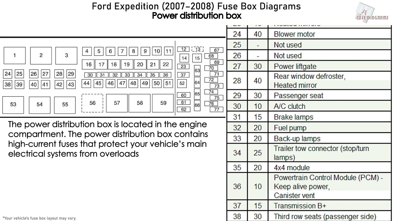
The 2003 Expedition typically has two main fuse boxes: one located inside the cabin (often under the dashboard on the driver's side) and another in the engine compartment (usually near the battery). Understanding their locations and contents is paramount.
- Cabin Fuse Box: This box primarily houses fuses for interior components like the radio, power windows, lights, and climate control.
- Engine Compartment Fuse Box: This box protects circuits related to engine management, starting, lighting, and other critical systems under the hood.
The diagram itself is essentially a grid showing the location of each fuse and relay, along with a legend indicating its function and amperage rating. Amperage is a measure of electrical current. Fuses are rated to break the circuit when the current exceeds a certain level, thus protecting the downstream components.
Key components listed on the diagram, and physically present in the fuse box, include:
- Fuses: These are the sacrificial links in the circuit. When too much current flows, the fuse's internal filament melts, breaking the circuit and preventing damage. They are rated in amps (e.g., 5A, 10A, 20A).
- Relays: These are electromechanical switches that allow a low-current circuit to control a high-current circuit. For example, a small switch on your dashboard activates a relay that then supplies power to your headlights.
- Circuit Breakers: Similar to fuses, but they can be reset. They are often used for high-current circuits that may experience temporary overloads.
Symbols, Lines, Colors, and Icons on the Diagram
Fuse box diagrams use a standardized set of symbols to represent different components and connections. Here's a breakdown of some common ones:
- Fuse Symbol: Typically a rectangle with a squiggly line inside. This represents the fuse itself.
- Relay Symbol: Usually a square with a coil symbol inside, often accompanied by switch-like symbols representing the relay's contacts.
- Ground Symbol: Resembles an upside-down tree or a series of horizontal lines decreasing in length. Indicates a connection to the vehicle's chassis ground.
- Lines: Solid lines indicate direct electrical connections. Dashed lines may indicate control signals or connections to other components.
- Colors: While not always consistent, some diagrams use colors to differentiate between power sources (e.g., red for positive, black for ground). However, always rely on the legend for definitive information.
- Icons: Small icons might represent the component the fuse protects (e.g., a headlight icon for the headlight fuse).
Understanding these symbols is crucial for interpreting the diagram accurately. Always refer to the legend provided with the diagram to confirm the meaning of each symbol and notation.
How It Works: Tracing a Circuit
The fuse box diagram allows you to trace a circuit from its power source to the component it powers. Here's a simplified explanation:
- Identify the Component: Let's say your radio isn't working. Find the listing for the radio in the diagram's legend.
- Locate the Fuse: The legend will tell you which fuse (identified by a number or code) protects the radio circuit. Find that fuse on the diagram.
- Trace the Circuit (Conceptually): Imagine the electrical current flowing from the battery, through the fuse, through the wiring, and finally to the radio. If the fuse is blown, the circuit is broken, and the radio receives no power.
Relays add a layer of complexity. For instance, the diagram might show that the headlights are powered by a relay. When you turn on the headlight switch, it sends a small electrical signal to the relay, which then closes the circuit and allows high-current power to flow to the headlights.
Real-World Use: Basic Troubleshooting Tips
Here's how to use the fuse box diagram to troubleshoot common electrical problems:
- Check for Blown Fuses: Visually inspect the fuse. A blown fuse will have a broken filament. Alternatively, use a multimeter to check for continuity across the fuse. A multimeter set to continuity test emits a beep if there is a connection.
- Replace with the Correct Fuse: Always replace a blown fuse with one of the exact same amperage rating. Using a higher amperage fuse can overload the circuit and cause a fire.
- If the Fuse Blows Again: If the replacement fuse blows immediately or shortly after being installed, there's likely a short circuit in the wiring or a problem with the component itself. This requires further investigation. It might involve inspecting the wiring harness for damage, checking the component for internal shorts, or consulting a professional mechanic.
- Check Relays: Relays can fail, too. You can sometimes diagnose a faulty relay by swapping it with a known good relay of the same type. If the problem disappears, the relay was the culprit. There are also relay testers available that can test the functionality of a relay.
Safety Precautions
Working with electrical systems can be dangerous. Here are some important safety precautions:
- Disconnect the Battery: Before working on the fuse box, disconnect the negative (-) terminal of the battery. This will prevent accidental short circuits and shocks.
- Use Proper Tools: Use insulated tools designed for electrical work.
- Identify High-Risk Components: Be especially careful around components related to the airbag system (SRS). Mishandling these components can cause accidental airbag deployment, which can be dangerous. The fuel pump relay is also a higher risk item, since fuel leaks can occur.
- Don't Overload Circuits: When adding aftermarket accessories, ensure you're not overloading the circuit. Consult the vehicle's wiring diagrams and calculate the total amperage draw of all components on the circuit.
- When in Doubt, Seek Professional Help: If you're uncomfortable working with electrical systems, consult a qualified mechanic.
Understanding the 2003 Ford Expedition's fuse box diagram is a valuable skill for any car owner. It empowers you to diagnose and fix minor electrical problems yourself, saving you time and money. Just remember to prioritize safety and use the correct tools and procedures.
Ready to get your hands on the full diagram? We have the complete 2003 Ford Expedition fuse box diagram available for download. You can use it to help with your repair!