Owner Manual 2003 Lincoln Navigator Fuse Box Diagram
Okay, let's dive into the 2003 Lincoln Navigator's fuse box diagram. This isn't just some pretty picture; it's your key to understanding and troubleshooting electrical problems in your SUV. Whether you're dealing with a blown fuse, planning some custom electrical work, or just trying to understand how everything's wired, having a solid grasp of this diagram is essential.
Purpose of the Fuse Box Diagram
Think of the fuse box diagram as the roadmap of your Navigator's electrical system. Its primary purpose is to provide a visual and symbolic representation of each fuse and relay within the fuse box. Why is this important? Here's a few reasons:
- Troubleshooting Electrical Issues: If your headlights aren't working, your power windows are stuck, or your radio's gone silent, the fuse box is often the first place to check. The diagram tells you which fuse protects each circuit, allowing you to quickly identify and replace a blown fuse.
- Preventing Electrical Overload: Each fuse is rated for a specific amperage. The diagram ensures you replace a blown fuse with the correct amperage rating. Using the wrong fuse can lead to electrical overloads, potentially damaging components or even causing a fire.
- Modifying Electrical Systems: Planning to add a new accessory, like a sound system or aftermarket lighting? The diagram helps you identify unused circuits or circuits that can safely handle the extra load.
- Understanding Your Vehicle: Even if you're not currently having problems, studying the fuse box diagram gives you a deeper understanding of how your Navigator's electrical systems are organized.
Key Specs and Main Parts
The 2003 Lincoln Navigator typically has two main fuse box locations:
- Under-Hood Fuse Box: Located in the engine compartment, this fuse box usually contains fuses and relays for critical systems like the engine management system (EMS), starting system, headlights, ABS, and power distribution.
- Interior Fuse Box: Usually found under the dashboard on the driver's side or in the passenger compartment, this box typically protects circuits related to interior features like power windows, power locks, radio, climate control, and interior lighting.
Each fuse box contains a collection of fuses and relays. Fuses are designed to protect individual circuits from overcurrent. Relays act as electrically operated switches, allowing a low-current circuit to control a high-current circuit. Key specs include:
- Fuse Amperage Ratings: Expressed in amps (A), fuse ratings indicate the maximum current a fuse can handle before blowing. Common ratings include 5A, 7.5A, 10A, 15A, 20A, 25A, 30A, and so on.
- Relay Types: Relays come in various types, including single-pole single-throw (SPST), single-pole double-throw (SPDT), and others. The diagram often indicates the type of relay and its function.
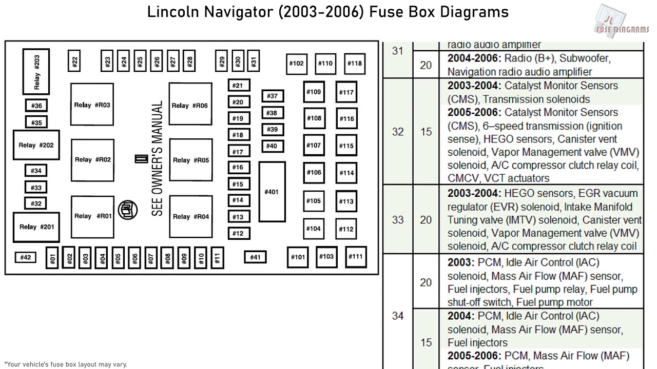
- Circuit Descriptions: The diagram will list the function of each fuse (e.g., "Headlights," "Fuel Pump," "Power Windows").
- Location Numbers/Labels: Each fuse and relay is assigned a unique number or label that corresponds to its location on the diagram.
Symbols, Lines, Colors, and Icons: Deciphering the Code
Understanding the symbols and conventions used in the fuse box diagram is crucial. Here's a breakdown:
- Fuses: Fuses are typically represented by a straight line between two terminals. The amperage rating is usually indicated next to the symbol.
- Relays: Relays are shown as a coil and a set of contacts. The coil represents the electromagnet that activates the relay, and the contacts represent the switch that controls the high-current circuit.
- Lines: Lines represent the electrical wires connecting different components. Thicker lines often indicate wires carrying higher current.
- Colors: Wire colors are sometimes indicated on the diagram, although this is less common in fuse box diagrams than in full wiring schematics. If present, the colors will be abbreviated (e.g., "BLU" for blue, "RED" for red, "BLK" for black).
- Icons: Specific icons may represent certain components, such as headlights, motors, or sensors. However, fuse box diagrams generally stick to basic fuse and relay symbols.
- Ground Symbols: A ground symbol indicates a connection to the vehicle's chassis, which serves as a common return path for electrical current.
Important Note: The exact symbols and conventions can vary slightly, so always refer to the legend or key provided with the diagram.
How It Works: Electrical Protection in Action
The fuse box is the central point for electrical protection in your Navigator. Here's how it works:
- Power Distribution: The battery provides power to the electrical system. This power is distributed to various circuits through the fuse box.
- Circuit Protection: Each circuit is protected by a fuse of the appropriate amperage rating. If the current in a circuit exceeds the fuse rating, the fuse's internal filament melts (the fuse "blows"), interrupting the circuit and preventing damage to components.
- Relay Control: Relays allow low-current circuits (like the ones controlled by switches on your dashboard) to control high-current circuits (like the headlights or starter motor). When the low-current circuit is energized, it activates the relay, which in turn closes the high-current circuit.
Real-World Use: Basic Troubleshooting Tips
Let's put this knowledge into practice. Here are some basic troubleshooting tips:
- Identify the Problem: Determine which system or component is not working.
- Consult the Diagram: Locate the fuse or relay associated with the malfunctioning system in the fuse box diagram.
- Inspect the Fuse: Remove the fuse and visually inspect it. If the filament is broken or the fuse looks burned, it's blown. You can also use a multimeter set to continuity to test the fuse. A working fuse will show continuity (a beep or a low resistance reading).
- Replace the Fuse: Replace the blown fuse with a new fuse of the exact same amperage rating. Never use a fuse with a higher rating.
- Test the System: After replacing the fuse, test the system to see if it's working properly.
- If the Fuse Blows Again: If the new fuse blows immediately, there's likely a short circuit or other underlying problem in the circuit. Further diagnosis is required.
- Relay Testing: Relays can be more challenging to test. You can try swapping a known good relay with the suspect relay to see if the problem resolves. However, a proper relay test usually requires a multimeter and knowledge of relay circuits.
Safety First: Highlighting Risky Components
Working with electrical systems can be dangerous. Here are some safety precautions:
- Disconnect the Battery: Before working on any electrical components, disconnect the negative battery terminal to prevent accidental shorts or shocks.
- Use Insulated Tools: Use tools with insulated handles to protect yourself from electric shock.
- Avoid Working in Wet Conditions: Never work on electrical systems in wet or damp environments.
- Identify High-Voltage Components: Be aware of high-voltage components, such as the ignition system and the alternator. Avoid touching these components when the engine is running.
- Don't Modify Fuse Ratings: Never replace a fuse with a higher amperage rating. This can overload the circuit and cause a fire.
- Seek Professional Help: If you're not comfortable working on electrical systems, consult a qualified mechanic.
Important Notes: Some systems such as the airbag system can cause significant harm if tampered with improperly. Always research safe practices before attempting any repairs.
You now have a good foundation for understanding and using the 2003 Lincoln Navigator's fuse box diagram. With a little practice and patience, you can confidently troubleshoot electrical problems and keep your Navigator running smoothly.
Remember safety is paramount, if you're ever unsure, consult a professional.
We have the full 2003 Lincoln Navigator Fuse Box Diagram available for download. This detailed diagram will be an invaluable resource for your electrical troubleshooting and repair projects.