Owner Manual 2005 Ford F150 Fuse Box Diagram
Alright, let's dive into the fuse box diagram for your 2005 Ford F-150. Consider this your roadmap to electrical troubleshooting and a crucial tool for anyone looking to understand their truck's inner workings. Whether you're dealing with a blown fuse, adding aftermarket accessories, or just expanding your automotive knowledge, having a solid grasp of the fuse box diagram is essential.
Purpose of the Fuse Box Diagram
Why bother with a fuse box diagram? Several key reasons: it's your first line of defense against electrical problems. When a component stops working – your radio, headlights, power windows – a blown fuse is often the culprit. The diagram allows you to quickly identify the correct fuse, saving you time and frustration. Beyond simple repairs, it's invaluable for:
- Troubleshooting Electrical Issues: The diagram helps you trace circuits and identify potential short circuits or overloaded systems.
- Installing Aftermarket Accessories: Planning to add a winch, auxiliary lights, or a new sound system? The diagram shows you where to tap into power and how to protect your new additions with appropriate fuses.
- Understanding Your Vehicle's Electrical System: Gaining a deeper understanding of how various components are powered and protected.
- Preventing Further Damage: Replacing a fuse with one of a higher amperage can lead to serious damage, including fires. The diagram ensures you use the correct fuse size.
Simply put, the fuse box diagram empowers you to diagnose and fix electrical issues yourself, saving money on costly mechanic visits and preventing further damage to your truck.
Key Specs and Main Parts
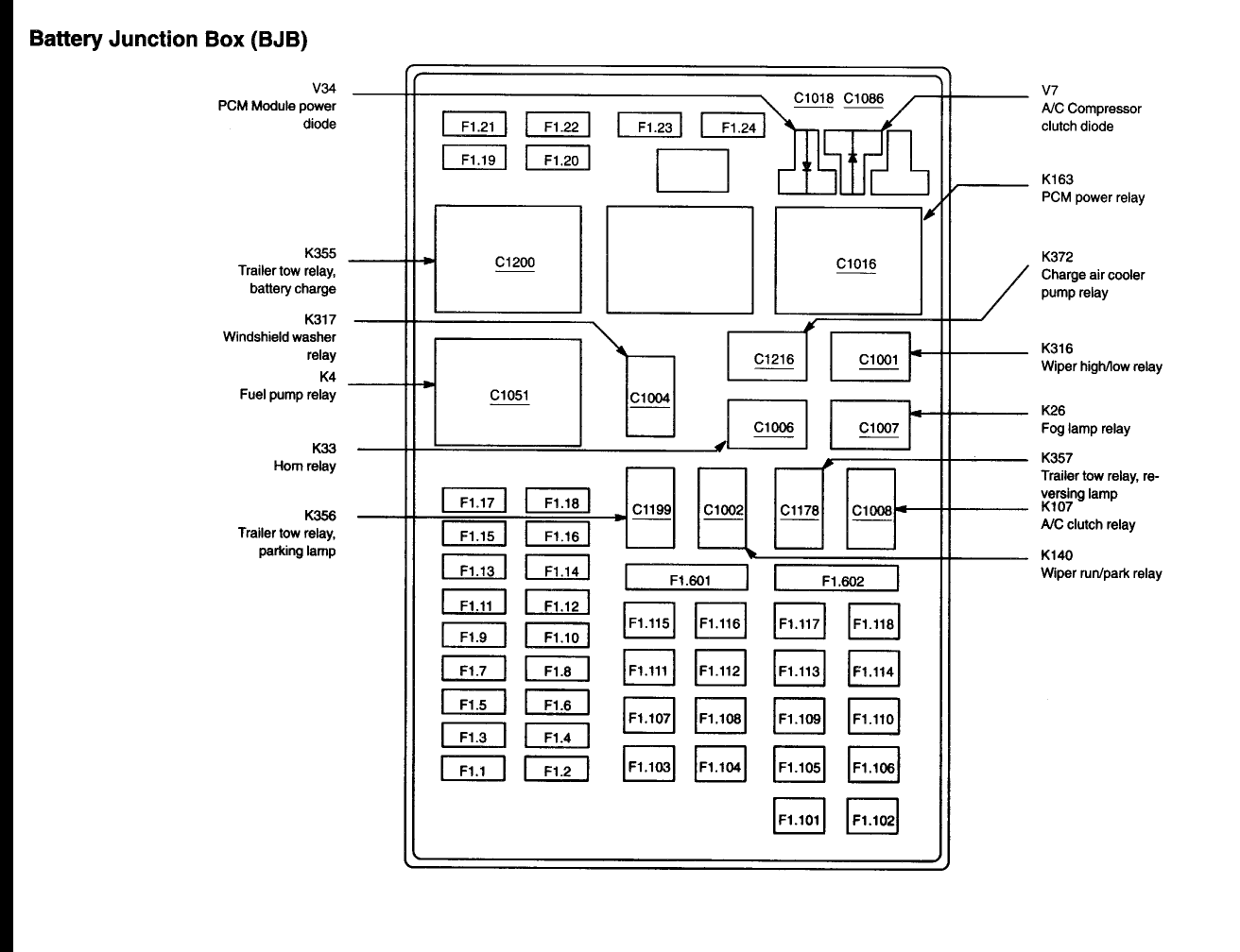
The 2005 Ford F-150 actually has two main fuse boxes: the interior fuse box (also called the Central Junction Box or CJB) located inside the cab, typically under the dashboard on the driver's side, and the under-hood fuse box (also called the Power Distribution Box or PDB) situated in the engine compartment. We have the diagram for both locations. Each box contains a collection of fuses and relays, each protecting a specific circuit or component.
Here's a breakdown of the key components:
- Fuses: These are the sacrificial links in your electrical circuits. They contain a thin wire designed to melt and break the circuit when the current exceeds a safe level. This protects the wiring and components from overheating and potential damage. Fuses are rated in amperes (amps), indicating the maximum current they can handle.
- Relays: These are electrically operated switches that allow a low-current circuit to control a high-current circuit. For example, the headlight relay allows the small switch on your dashboard to control the high-current headlights. Relays are identified by their function (e.g., headlight relay, fuel pump relay).
- Fuse Box Housing: This plastic housing protects the fuses and relays from the elements and provides a secure mounting point.
- Fuse Puller: A small plastic tool used to safely remove and install fuses. Often located inside one of the fuse boxes.
- Diagram Label: Typically found on the inside of the fuse box cover, this label provides a map of the fuse and relay locations, along with their corresponding circuits and amperage ratings. This is the diagram we are focusing on.
Decoding the Symbols
The fuse box diagram isn't just a random assortment of numbers and lines. It uses a standardized set of symbols and conventions to convey information. Understanding these symbols is key to interpreting the diagram correctly.
- Lines: Represent electrical circuits. A solid line typically indicates a direct connection. Dotted lines may indicate a ground connection or a connection to a module.
- Numbers: Indicate the fuse number. This is crucial for identifying the correct fuse on the physical fuse box.
- Ampere Ratings (e.g., 5A, 10A, 20A): Indicate the current capacity of the fuse. Never replace a fuse with a higher amperage rating.
- Icons: Represent the component or circuit protected by the fuse. Common icons include headlights, taillights, radio, power windows, etc.
- Colors: Although less common in older diagrams like the 2005 F-150, some diagrams use colors to differentiate between circuit types (e.g., red for power, black for ground).
The diagram will also include a key or legend that explains any specific symbols or abbreviations used. Pay close attention to this legend, as it can vary slightly between different diagrams.
How It Works
The fuse box acts as a central distribution point for electrical power in your F-150. Power from the battery is routed through the fuse box, where it's distributed to various circuits, each protected by its own fuse. When a circuit experiences an overload (too much current), the fuse blows, interrupting the flow of electricity and preventing damage to the circuit and its components.
The diagram allows you to trace the path of electricity from the battery to a specific component. For example, if your headlights aren't working, you can use the diagram to identify the headlight fuse, check its condition, and, if necessary, replace it. If the fuse blows repeatedly, it indicates a more serious problem in the headlight circuit, such as a short circuit or a faulty component. In that instance, further diagnostics is needed.
Relays, as mentioned earlier, act as remote-controlled switches. They're used to control high-current circuits with low-current signals. The diagram shows you which relay controls which circuit, allowing you to diagnose relay-related problems. For example, if your fuel pump isn't working, you can use the diagram to locate the fuel pump relay and test its functionality.
Real-World Use: Basic Troubleshooting Tips
Here's how to put the fuse box diagram to work:
- Identify the Problem: Determine which component isn't working.
- Consult the Diagram: Locate the fuse or relay associated with the faulty component.
- Inspect the Fuse: Use a fuse puller to remove the fuse and visually inspect it. A blown fuse will have a broken filament. You can also use a multimeter to test for continuity across the fuse.
- Replace the Fuse: If the fuse is blown, replace it with a new fuse of the exact same amperage rating. Never use a higher amperage fuse.
- Test the Component: After replacing the fuse, test the component to see if it's working.
- If the Fuse Blows Again: If the new fuse blows immediately or soon after, there's a problem in the circuit. This could be a short circuit, a faulty component, or an overloaded circuit. Further diagnosis is required.
For relays, you can test them by swapping them with a known good relay from a less critical circuit (e.g., the windshield washer relay). If the problem moves to the circuit controlled by the swapped relay, the original relay is faulty.
Safety Considerations
Working with electrical systems can be dangerous. Always observe the following safety precautions:
- Disconnect the Battery: Before working on any electrical components, disconnect the negative terminal of the battery to prevent accidental short circuits.
- Use the Correct Fuses: Never replace a fuse with a higher amperage rating. Doing so can overload the circuit and cause a fire.
- Avoid Water: Never work on electrical systems in wet conditions.
- Be Aware of Airbags: Airbag circuits are highly sensitive. Avoid tampering with these circuits unless you're a qualified technician. Incorrect handling can cause the airbags to deploy, resulting in serious injury.
- Capacitors: Be aware that some electronic components, such as those in the radio or PCM, can store electrical charge even after the battery is disconnected. Allow sufficient time for these components to discharge before handling them.
High-amperage fuses such as those protecting the ABS system or PCM are potentially more dangerous. Mishandling these circuits could result in significant electrical shock.
Having a good understanding of your 2005 F-150's fuse box diagram is invaluable for troubleshooting electrical issues, installing aftermarket accessories, and gaining a deeper understanding of your truck's electrical system. By following the safety precautions outlined above, you can work safely and effectively on your vehicle's electrical system.
We have the complete fuse box diagrams, for both the interior and engine compartment fuse boxes, available for download. Use it wisely and happy wrenching!