Owner Manual 2006 Ford F150 Fuse Box Diagram
The fuse box diagram for your 2006 Ford F-150 is arguably one of the most important pieces of documentation you can have access to, especially if you're a seasoned DIYer tackling electrical repairs or adding aftermarket components. Understanding this diagram isn't just about knowing which fuse to replace; it’s about understanding the electrical architecture of your truck, empowering you to diagnose problems efficiently, avoid costly shop visits, and even safely customize your vehicle.
Purpose of the Fuse Box Diagram
Why should you bother with this diagram? Here are the main reasons:
- Troubleshooting Electrical Issues: When something electrical stops working – a headlight, the radio, the windshield wipers – the first place to look is the fuse box. The diagram tells you which fuse corresponds to that specific circuit.
- Preventing Further Damage: Replacing a blown fuse with a higher amperage fuse is a recipe for disaster. The diagram ensures you use the correct replacement, preventing potentially serious electrical fires or damage to sensitive electronic components.
- Adding Aftermarket Accessories: Planning to install a new stereo, auxiliary lights, or a trailer brake controller? The fuse box diagram helps you identify suitable circuits for tapping into power, minimizing the risk of overloading existing systems.
- Understanding Vehicle Systems: Even if you're not actively troubleshooting, studying the diagram can give you a better understanding of how your F-150's electrical system is designed and how different components are interconnected.
Key Specs and Main Parts of the 2006 F-150 Fuse Box
The 2006 F-150 actually has two main fuse boxes. It’s crucial to understand both locations and their roles.
- The Interior Fuse Box: Located on the passenger side, usually behind a panel near the glove box. This fuse box primarily handles circuits for interior components, such as the radio, lights, power windows, and climate control.
- The Engine Compartment Fuse Box (Power Distribution Box): Situated under the hood, typically near the battery. This box contains fuses and relays responsible for high-current systems like the engine control unit (ECU), headlights, starter motor, and anti-lock braking system (ABS).
Key Specifications to Note:
- Fuse Amperage Ratings: Fuses are rated in amps (A), indicating the maximum current they can handle before blowing. Common ratings include 5A, 7.5A, 10A, 15A, 20A, 25A, 30A, and higher. Always replace a blown fuse with one of the same amperage.
- Fuse Types: The 2006 F-150 typically uses blade-type fuses. These are small, color-coded fuses with two prongs. There may be mini, regular, and maxi blade fuses, each with different physical sizes.
- Relays: Relays are electromechanical switches that control high-current circuits using a low-current signal. They are often used to switch headlights, the starter motor, and other power-hungry components. The Power Distribution Box contains various relays.
Decoding the Symbols: Lines, Colors, and Icons
Fuse box diagrams aren't just a list of fuses; they use symbols and conventions to represent electrical connections and component functions. Understanding these symbols is essential for accurate interpretation.
- Lines: Solid lines represent electrical wires. Thicker lines often indicate circuits carrying higher currents. Dotted lines may indicate grounding paths or signal circuits.
- Colors: Wire colors are often indicated on the diagram using abbreviations (e.g., "RD" for red, "BL" for blue, "BK" for black). These colors can help you trace wires within the vehicle.
- Icons: Icons represent the components protected by each fuse. Common icons include:
- Headlight Symbol: Identifies the fuse for the headlights.
- Radio Symbol: Identifies the fuse for the radio.
- Cigarette Lighter Symbol: Identifies the fuse for the cigarette lighter/power outlet.
- Windshield Wiper Symbol: Identifies the fuse for the windshield wipers.
- Engine Symbol: Can indicate a fuse related to the engine control unit (ECU).
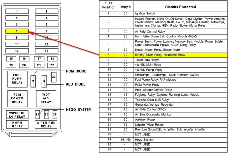
- Fuse Number and Function: Each fuse location is typically labeled with a number and a brief description of its function (e.g., "Fuse #20: Radio").
It's crucial to consult the specific diagram for your 2006 F-150, as there may be slight variations depending on the trim level and optional equipment.
How It Works: Basic Circuit Operation
At its heart, a fuse is a simple safety device designed to protect an electrical circuit from overcurrent. Here's how it works:
- Current Flow: Electricity flows from the battery, through the wiring, through the fuse, and then to the component it's powering (e.g., a headlight).
- Fuse Element: Inside the fuse is a thin wire or strip of metal called the fuse element. This element is designed to melt and break the circuit if the current exceeds the fuse's amperage rating.
- Overcurrent Protection: If a short circuit occurs (e.g., a wire rubs against the chassis, creating a low-resistance path to ground) or if a component draws excessive current, the current flow increases dramatically.
- Fuse Blows: The excessive current causes the fuse element to overheat and melt, breaking the circuit and stopping the flow of electricity. This prevents the wiring from overheating and potentially causing a fire.
Think of a fuse like a dam. It holds back the flow of water (electricity) until a certain level is reached. If the water level gets too high, the dam breaks, preventing a catastrophic flood (electrical fire).
Real-World Use: Basic Troubleshooting Tips
Here's a step-by-step approach to troubleshooting using the fuse box diagram:
- Identify the Problem: Determine which electrical component is not working.
- Consult the Diagram: Locate the fuse box diagram for your 2006 F-150 (remember, there are two!). Find the fuse that corresponds to the malfunctioning component.
- Inspect the Fuse: Remove the fuse using a fuse puller (a small plastic tool designed to grip and remove fuses). Visually inspect the fuse. If the fuse element is broken or blackened, the fuse is blown.
- Test the Fuse: While visual inspection is helpful, it's not always definitive. Use a multimeter set to continuity mode to test the fuse. A working fuse will show continuity (a beep or a low resistance reading). A blown fuse will show no continuity.
- Replace the Fuse: Replace the blown fuse with a new fuse of the same amperage rating. Never use a higher amperage fuse.
- Test the Component: Turn on the component to see if it now works.
- If the Fuse Blows Again: If the new fuse blows immediately, there is a short circuit or overload in the circuit. Further diagnosis is required to locate and repair the underlying problem. This may involve checking wiring for damage, testing components, or consulting a qualified mechanic.
Important Note: Repeatedly replacing a blown fuse without addressing the underlying issue is a dangerous practice and can lead to serious electrical damage.
Safety First: Risky Components and Precautions
Working with automotive electrical systems can be dangerous if proper precautions are not taken. Keep these points in mind:
- Disconnect the Battery: Before working on any electrical system, disconnect the negative battery cable. This prevents accidental shorts and reduces the risk of electric shock.
- High-Current Circuits: Be especially cautious when working with circuits protected by high-amperage fuses (e.g., those in the Power Distribution Box). These circuits can deliver a significant amount of current, posing a shock hazard.
- Airbag System: The airbag system is electrically triggered. Tampering with the wiring or fuses associated with the airbag system can cause accidental deployment, resulting in serious injury. If you suspect an issue with the airbag system, consult a qualified mechanic.
- Fuel Pump Circuit: The fuel pump circuit carries potentially flammable fuel. Take extra precautions when working on this circuit to avoid sparks or sources of ignition.
- Proper Tools: Use insulated tools and a multimeter designed for automotive use.
Disclaimer: This information is for general guidance only and should not be considered a substitute for professional advice. Always consult a qualified mechanic if you are unsure about any aspect of automotive electrical repair.
We have the complete 2006 Ford F-150 fuse box diagrams available for download. This resource provides a detailed visual guide, making troubleshooting and modifications easier than ever before.