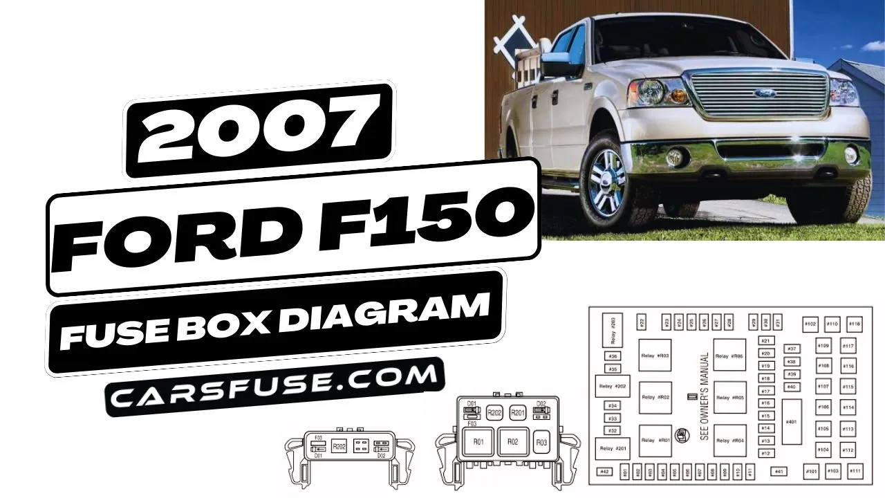
Owner Manual 2007 Ford F150 Fuse Box Diagram
Let's dive into the 2007 Ford F-150 fuse box diagram. This isn't just some piece of paper; it's a critical tool for anyone working on their F-150's electrical system. Whether you're tackling a malfunctioning radio, installing aftermarket accessories, or chasing down a mysterious short, understanding this diagram is paramount. It empowers you to diagnose and fix electrical issues safely and efficiently, saving you time and potentially a hefty bill from a mechanic.
Purpose: Your Electrical Roadmap
The fuse box diagram serves as a detailed map of your truck's electrical circuits. Its main purposes include:
- Troubleshooting Electrical Issues: Quickly identify the fuse associated with a specific component (e.g., headlights, power windows) that isn't working.
- Locating Faults: Determine if a blown fuse is the root cause of a problem or merely a symptom of a larger issue (e.g., a short circuit).
- Installing Aftermarket Accessories: Identify appropriate circuits to tap into for powering new devices like lights, amplifiers, or auxiliary power outlets.
- Understanding Circuit Protection: Grasp how fuses protect your vehicle's sensitive electronic components from overcurrents and potential damage.
In essence, the diagram transforms a complex web of wires and electrical components into a manageable and understandable system.
Key Specs and Main Parts
The 2007 F-150 typically has two main fuse boxes:
- Battery Junction Box (BJB): Located under the hood, usually near the battery. This houses high-amperage fuses and relays that control major systems like the engine, starter motor, and anti-lock braking system (ABS).
- Central Junction Box (CJB): Located inside the cab, often under the dashboard or behind a kick panel. This handles lower-amperage circuits for interior components like the radio, lights, and power accessories.
Key specifications to note:
- Fuse Amperage Ratings: Each fuse is rated for a specific current (measured in amperes or amps, denoted by "A"). This rating indicates the maximum current the fuse can handle before it blows, protecting the circuit from overload. Common ratings include 5A, 7.5A, 10A, 15A, 20A, 25A, 30A, and higher.
- Circuit Descriptions: The diagram lists the component or system protected by each fuse. These descriptions can range from general terms ("Interior Lights") to more specific ones ("Fuel Pump Relay").
- Relay Locations: The diagram also identifies the location and function of various relays, which are electromechanical switches used to control high-current circuits with a low-current signal. Relays often control things like the fuel pump, starter, and headlights.
- Fuse Type: Mini (blade) fuses are used in the 2007 F150.
It's crucial to have the correct diagram for your specific F-150 configuration, as fuse assignments and locations can vary slightly depending on the trim level, engine type, and optional equipment.
Symbols: Decoding the Diagram
Understanding the symbols and conventions used in the fuse box diagram is essential for accurate interpretation:
- Lines: Solid lines represent wiring connections. Dashed lines may indicate internal connections within a component or a shielded cable.
- Fuse Symbol: Typically a squiggly line inside a rectangle. The number next to the symbol indicates the fuse's amperage rating.
- Relay Symbol: Usually a square or rectangle with internal markings to represent the coil and contacts.
- Color Codes: While the diagram itself may not be in color, understanding Ford's wiring color codes can be helpful. For example, a "WH/GN" wire is white with a green stripe. Use a wiring diagram and schematic to troubleshoot.
- Connector Symbols: Circles or other shapes with numbers or letters inside indicate wiring connectors. These can be helpful for identifying the location of specific wiring harnesses.
- Ground Symbol: A downward-pointing arrow symbol indicates a ground connection, where the circuit is connected to the vehicle's chassis for a return path.
Pay close attention to the legend or key on the diagram, as it will explain any unique symbols or abbreviations used. Always refer to the legend first if you are unsure what a symbol represents.
How It Works: A Simplified Explanation
The electrical system in your F-150 operates on the principle of a closed circuit. Electricity flows from the battery, through a wire, to a component (e.g., a light bulb), and then back to the battery through another wire or the vehicle's chassis (ground). The fuse is inserted into this circuit as a safety device. If an excessive amount of current flows through the circuit (due to a short circuit or an overloaded component), the fuse's internal filament melts, breaking the circuit and stopping the flow of current. This prevents damage to the wiring, the component, and potentially the vehicle itself.
Relays act as remote switches. A low-current signal from a switch inside the cab (e.g., the headlight switch) activates the relay's coil, which in turn closes the relay's contacts and allows a high-current circuit to power the headlights directly from the battery. This prevents the headlight switch from having to handle the high current, which could damage it.
Real-World Use: Basic Troubleshooting
Here's how to use the fuse box diagram for basic troubleshooting:
- Identify the Problem: Determine which component or system is malfunctioning (e.g., the cigarette lighter isn't working).
- Consult the Diagram: Locate the fuse associated with that component in the fuse box diagram. The correct fuse location will be labeled in the diagram.
- Inspect the Fuse: Visually inspect the fuse. If the filament inside the fuse is broken, the fuse is blown and needs to be replaced.
- Replace the Fuse: Replace the blown fuse with a new fuse of the same amperage rating. Never use a fuse with a higher amperage rating, as this could overload the circuit and cause damage or even a fire.
- Test the System: After replacing the fuse, test the component or system to see if it's working again.
- Investigate Further: If the fuse blows again immediately or shortly after being replaced, there is likely a short circuit or other underlying problem in the circuit that needs to be investigated.
Using a multimeter can help in more advanced diagnostics to check for voltage, continuity, and current flow.
Safety: Proceed with Caution
Working with electrical systems can be dangerous. Here are some safety precautions to follow:
- Disconnect the Battery: Before working on any electrical components, disconnect the negative (-) terminal of the battery to prevent accidental shocks or short circuits.
- Use Insulated Tools: Always use tools with insulated handles to protect yourself from electrical shock.
- Be Aware of High-Voltage Components: Be especially cautious around components like the ignition system and the air conditioning system, which can contain high voltages even after the engine is turned off.
- Never Bypass a Fuse: Never bypass a fuse by using a wire or other conductive material. This eliminates the circuit protection and can lead to serious damage or a fire.
- If unsure, consult a professional: If you are not comfortable working on electrical systems or are unsure about any aspect of the repair, seek the help of a qualified mechanic.
The BJB under the hood contains higher amperage circuits that feed critical components. A fault in these circuits can lead to bigger problems, so approach troubleshooting here with extra caution.
With this guide and the fuse box diagram, you're well-equipped to tackle many electrical issues on your 2007 Ford F-150. Remember safety first, and don't hesitate to consult a professional if you're unsure.
We have the 2007 Ford F150 Fuse Box Diagram file. You can download the diagram here.