Owner Manual 2010 Ford F150 Fuse Box Diagram
Hey there, fellow wrench-turners! Today, we’re diving deep into the often-overlooked but critically important world of fuse boxes in the 2010 Ford F-150. Specifically, we'll be dissecting the owner's manual fuse box diagram. Understanding this diagram isn't just about replacing a blown fuse; it's about gaining a crucial understanding of your truck's electrical system, enabling you to perform repairs, diagnose issues, and even safely add aftermarket modifications.
Purpose of the Fuse Box Diagram
Let's be honest: the fuse box diagram isn’t exactly bedtime reading. But its utility is undeniable. Here's why it's a valuable resource:
- Troubleshooting Electrical Issues: When an electrical component fails (lights, radio, power windows, etc.), the first place you should look is the fuse box. The diagram pinpoints the exact fuse associated with that circuit, allowing for quick identification and replacement.
- Preventing Further Damage: Replacing a blown fuse with one of the same amperage rating protects the rest of the circuit from potential overloads and damage to other, more expensive components. A correct diagram ensures you're replacing the correct fuse.
- Adding Aftermarket Accessories: Thinking of installing a new sound system, auxiliary lights, or a winch? A proper understanding of the fuse box and available circuits is essential for safely integrating these accessories into your truck's electrical system. You need to identify appropriate circuits and fuse ratings to avoid overloading the system.
- General Understanding: Even if you aren't experiencing problems, familiarizing yourself with the fuse box diagram gives you a broader understanding of how your truck's electrical system is structured and protected.
Key Specs and Main Parts
The 2010 Ford F-150 typically has two main fuse boxes:
- Battery Junction Box (BJB): Located in the engine compartment, usually near the battery. This box houses higher-amperage fuses and relays that protect critical circuits, such as the starter motor, alternator, and main power distribution.
- Smart Junction Box (SJB): Located inside the cab, often under the dashboard or behind a kick panel. This box handles lower-amperage circuits related to interior functions like lights, radio, power windows, and the instrument cluster.
The owner's manual fuse box diagram will provide a detailed layout of each of these boxes, including:
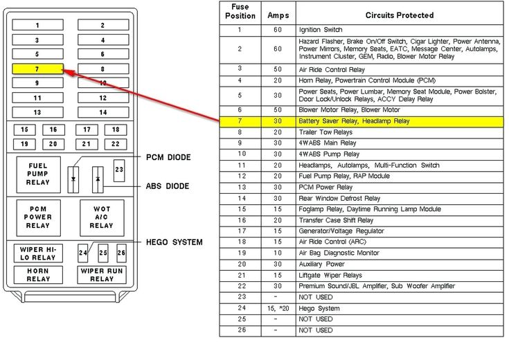
- Fuse Locations: A grid or map showing the physical position of each fuse within the box.
- Fuse Numbers: A unique identifying number assigned to each fuse.
- Circuit Description: A brief description of the circuit protected by each fuse (e.g., "Left Headlight," "Radio," "Power Windows").
- Fuse Ampere Rating: The maximum current (measured in amperes, or amps) that the fuse is designed to carry before it blows and interrupts the circuit. This is crucial. Never replace a fuse with a higher amperage rating.
- Relay Locations: The diagram also shows relays, which are electromechanical switches controlling higher-current circuits (e.g., starter relay, fuel pump relay).
Symbols – Understanding the Language
Fuse box diagrams use a specific set of symbols and conventions to convey information effectively. Here's a breakdown:
- Fuse Representation: Fuses are typically represented by a rectangular shape with a zigzag line running through it. This zigzag line symbolizes the fusible element within the fuse.
- Relay Representation: Relays are usually represented by a square or rectangular shape with a coil symbol and switch contacts. The coil symbol indicates the electromagnet that controls the switch.
- Lines: Lines connecting fuses and relays indicate the electrical connections between components. Heavier lines might represent higher-current carrying wires.
- Colors: Color-coding can be used to differentiate between different types of circuits or voltage levels. Consult your owner's manual for specific color-coding used in your truck's fuse box diagrams.
- Icons: Some diagrams may use icons to represent the specific components protected by each fuse (e.g., a light bulb icon for headlight fuses, a speaker icon for radio fuses).
How It Works
The fuse box is essentially a central distribution point for electrical power in your truck. Power from the battery flows to the fuse boxes, where it's divided into individual circuits, each protected by a fuse. Each fuse contains a thin wire designed to melt and break the circuit if the current exceeds the fuse's amperage rating.
Think of it like this: each circuit is like a water pipe, and the fuse is like a narrow section in the pipe. If too much water (current) flows through the pipe, the narrow section (fuse) breaks, preventing damage to the rest of the system. This sacrificial action protects expensive components from overloads and potential fires.
Real-World Use – Basic Troubleshooting Tips
Here’s how to use the fuse box diagram to solve common electrical problems:
- Identify the Problem: Determine which electrical component isn't working.
- Consult the Diagram: Locate the fuse associated with that component in the owner's manual fuse box diagram.
- Inspect the Fuse: Remove the fuse from the fuse box and visually inspect it. Look for a broken filament or a darkened glass (in the case of glass fuses). A fuse puller (often found in the fuse box) makes this easier.
- Test the Fuse (Optional): For a more accurate test, use a multimeter in continuity mode. If the multimeter shows no continuity (open circuit), the fuse is blown.
- Replace the Fuse: Replace the blown fuse with a new fuse of the exact same amperage rating.
- Test the Component: Turn on the component to see if it now works. If the new fuse blows immediately, there's a more serious problem in the circuit that needs further diagnosis (short circuit, wiring fault, etc.).
Example: Your headlights aren't working. You consult the owner's manual fuse box diagram and find that fuse #22 in the BJB (Battery Junction Box) is labeled "Right Headlight." You remove fuse #22 and see that the filament is broken. You replace it with a new fuse of the same amperage rating, and the headlights now work. Problem solved!
Safety – Handle with Care
Working with electrical systems can be dangerous. Here are some crucial safety precautions:
- Disconnect the Battery: Before working on any electrical component, disconnect the negative terminal of the battery to prevent accidental shorts and electrical shock. This is especially important when dealing with the BJB, which carries higher currents.
- Use the Right Tools: Use insulated tools designed for electrical work.
- Never Bypass a Fuse: Never bypass a fuse with a wire or any other conductive material. This eliminates the circuit protection and can lead to overheating, fires, and damage to components.
- Handle Capacitors with Caution: Some electrical components, like those in the SJB, may contain capacitors that can store a charge even after the battery is disconnected. Avoid touching exposed terminals or components without discharging them first (usually done by shorting the terminals with a resistor).
- Work in a Well-Lit Area: Ensure you have adequate lighting to see what you're doing clearly.
- Consult a Professional: If you're uncomfortable working with electrical systems or encounter complex problems, consult a qualified mechanic or electrician.
High-Risk Components: The BJB, containing high-amperage fuses and relays controlling critical engine functions, is a higher-risk area. Exercise extreme caution when working around this box, ensuring the battery is disconnected and you have a clear understanding of the circuits involved.
Final Thoughts
The 2010 Ford F-150 fuse box diagram is your roadmap to understanding and maintaining your truck’s electrical system. By understanding its purpose, interpreting its symbols, and following safe practices, you can confidently tackle basic electrical repairs and modifications. Remember to always use the correct fuse amperage rating, disconnect the battery before working on electrical components, and consult a professional if you're unsure about anything.
We have the complete 2010 Ford F-150 owner's manual, including the fuse box diagram, available for download. Click the link below to get your copy and keep it handy for all your future electrical troubleshooting needs. Happy wrenching!