Owners Manual 2013 Chrysler 200 Fuse Box Diagram
Alright, let's dive into the fuse box diagram for your 2013 Chrysler 200. This isn't just a pretty picture; it's your roadmap to understanding and maintaining the electrical system of your car. Whether you're dealing with a blown fuse, planning an upgrade, or simply want to be more familiar with your vehicle's inner workings, this diagram is essential. We'll break down everything you need to know, from the basic layout to real-world troubleshooting.
Purpose of the Fuse Box Diagram
The fuse box diagram serves several crucial purposes:
- Troubleshooting Electrical Problems: When something electrical malfunctions – a taillight goes out, the radio stops working, or the power windows refuse to budge – the first thing you should check is the fuse box. The diagram helps you locate the specific fuse responsible for that circuit.
- Identifying Fuse Ratings: The diagram, often combined with information printed on the fuse box itself, indicates the amperage rating (the amount of electrical current a fuse can handle before blowing) for each fuse. Using the correct rating is critical for safety and proper operation. An incorrect fuse can lead to either constant blowing or, much worse, an electrical fire.
- Adding Aftermarket Accessories: Planning to install a new sound system, fog lights, or a dashcam? The fuse box is often the best place to tap into the vehicle's electrical system. The diagram allows you to identify suitable circuits and ensure you're not overloading anything.
- General Understanding: Even if you don't have a specific problem, studying the diagram helps you understand how different systems in your car are connected and protected. This can be invaluable for future repairs or modifications.
Key Specs and Main Parts
The 2013 Chrysler 200 typically has two main fuse boxes:
- Under-Hood Fuse Box (Power Distribution Center): Located in the engine compartment, this box contains fuses and relays that protect major systems like the engine control module (ECM), anti-lock braking system (ABS), headlights, and cooling fans. It's responsible for handling high-current circuits.
- Interior Fuse Box (Junction Block): Usually found under the dashboard, either on the driver's or passenger's side, this box houses fuses for interior components such as the radio, power windows, climate control, and cigarette lighter (if equipped). These circuits generally draw less current than those in the under-hood fuse box.
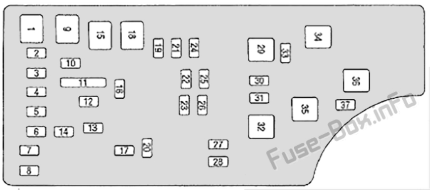
The diagram itself is a representation of these boxes, showing the location of each fuse and relay. It also includes a legend that explains the function of each component.
Symbols: Lines, Colors, and Icons
Understanding the symbols on the diagram is key to deciphering its meaning. Here's a breakdown of common elements:
- Lines: Solid lines typically represent the electrical circuits. Thicker lines might indicate higher current capacity. Dashed lines could indicate a ground connection or a signal path.
- Colors: While not always present on printed diagrams, some digital versions might use color-coding to represent different voltage levels or system categories. For example, red could indicate circuits connected directly to the battery, while blue might represent circuits switched by the ignition.
- Icons: These are pictorial representations of the components protected by each fuse. Common icons include:
- Headlight: Indicates the headlight circuit.
- Radio: Indicates the radio or audio system circuit.
- Windshield Wiper: Indicates the windshield wiper circuit.
- Horn: Indicates the horn circuit.
- Engine Symbol: Indicates engine management system circuits.
- Square with a zigzag: Represents a relay. Relays are electrically operated switches that allow a low-current circuit to control a high-current circuit.
- Numbers: Each fuse location is numbered or labeled, allowing you to cross-reference the diagram with the actual fuse box. These numbers are critical for finding the correct fuse.
The legend on the diagram provides a more detailed explanation of each symbol and its corresponding function. Always refer to the legend for clarification.
How It Works: Electrical Flow and Fuse Protection
The fuse box acts as a central distribution point for electrical power throughout the vehicle. Power from the battery flows through the fuses and relays to various components. Each fuse is designed to protect a specific circuit by interrupting the flow of current if it exceeds a predetermined level. This prevents damage to the wiring and components connected to that circuit. This is where the amperage rating becomes so important.
Think of it like this: each fuse is a thin wire designed to melt if too much current passes through it. When a fuse blows, it indicates a fault somewhere in the circuit it protects, such as a short circuit or an overloaded component.
Real-World Use: Basic Troubleshooting Tips
Here’s how to use the fuse box diagram for basic troubleshooting:
- Identify the Problem: Determine which component is malfunctioning.
- Locate the Fuse Box: Consult your owner's manual to find the location of the relevant fuse box (under-hood or interior).
- Consult the Diagram: Use the diagram to identify the fuse associated with the malfunctioning component.
- Inspect the Fuse: Use a fuse puller (usually included in the fuse box) to remove the fuse. Visually inspect it for a broken filament. A blown fuse will have a visible gap in the thin wire inside. You can also use a multimeter set to continuity mode to test the fuse. If the multimeter doesn't beep or show continuity (usually indicated by a "0" or very low number), the fuse is blown.
- Replace the Fuse: If the fuse is blown, replace it with a new fuse of the exact same amperage rating. Do not use a higher amperage fuse, as this could damage the circuit and potentially cause a fire.
- Test the System: After replacing the fuse, test the component to see if it now functions correctly.
- If the Fuse Blows Again: If the new fuse blows immediately or shortly after being replaced, it indicates a more serious problem in the circuit. This could be a short circuit, a faulty component, or damaged wiring. In this case, it's best to consult a qualified mechanic.
Safety: Highlighting Risky Components
Working with electrical systems can be dangerous. Here are some safety precautions to keep in mind:
- Disconnect the Battery: Before working on the fuse box, disconnect the negative (-) terminal of the battery to prevent accidental shorts.
- Use the Correct Fuse Rating: Always replace a blown fuse with a fuse of the same amperage rating. Using a higher-rated fuse can overload the circuit and cause a fire.
- Avoid Working in Wet Conditions: Water conducts electricity, so avoid working on the fuse box in wet or damp environments.
- Be Careful with Relays: Relays can contain capacitors that store electrical charge even after the battery is disconnected. Avoid touching the terminals of relays unless you are sure they are discharged.
- Seek Professional Help: If you are uncomfortable working with electrical systems or if you suspect a more serious problem, consult a qualified mechanic. Messing with the wrong circuit, especially in safety-critical systems like ABS or airbags, can have serious consequences.
- High-Current Circuits: Be particularly cautious when dealing with fuses and relays related to high-current systems like the starter motor, alternator, and cooling fans. These circuits can carry significant amounts of electricity and pose a greater risk of electric shock or burns.
Remember, electrical systems are complex. If you're unsure about anything, it's always best to err on the side of caution and seek professional assistance.
We have a detailed 2013 Chrysler 200 fuse box diagram file available for download. Having a digital copy can be incredibly useful for zooming in on specific sections and searching for particular components. Feel free to download it and keep it handy for future reference. Just remember to use it responsibly and always prioritize safety.