Parts Of A Car Body Diagram
Let's dive into the world of car body diagrams, also known as body structure diagrams or collision repair diagrams. These aren't just pretty pictures; they're essential tools for anyone involved in auto repair, modification, or even just understanding the skeleton of their vehicle. Think of it as an anatomical chart for your car, showing you exactly what's underneath the paint and trim.
Purpose: Why Bother with a Car Body Diagram?
Why should you, as an experienced DIYer or modder, care about these diagrams? Here's the gist:
- Accurate Repairs: When dealing with collision damage, a body diagram is your bible. It precisely illustrates the location of structural components, allowing for accurate measurements and repairs. No more guesswork!
- Modification Planning: Planning to add aftermarket parts or modify the body? A diagram reveals load-bearing points, potential interference issues, and structural limitations.
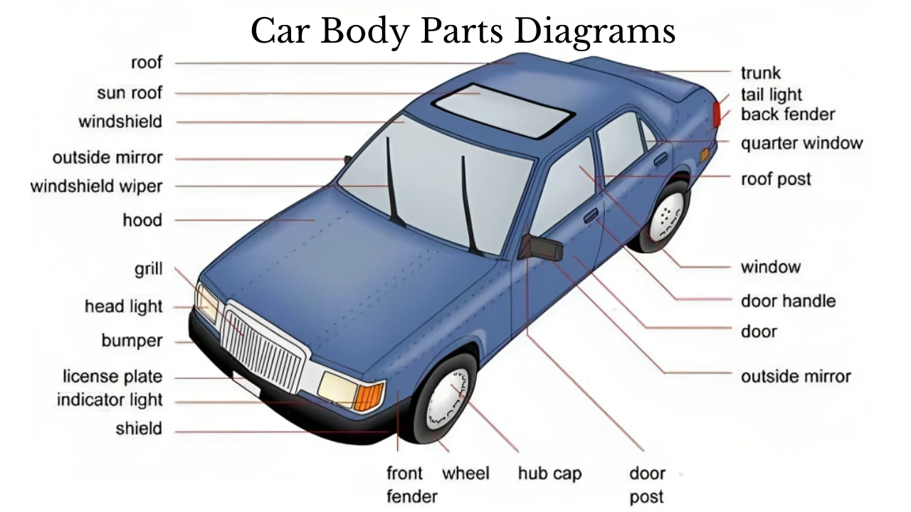
- Component Identification: Ever wonder what that piece of metal is called under the fender? Diagrams label almost every panel, brace, and reinforcement.
- Troubleshooting: Diagnosing issues like squeaks, rattles, or misaligned panels becomes easier when you understand the underlying structure.
- Learning and Understanding: Simply put, diagrams enhance your understanding of how a car is built, its crashworthiness, and its overall design.
Key Specs and Main Parts: Decoding the Diagram
A typical car body diagram presents a multi-layered view of the vehicle's structure. Key components include:
Structural Members:
These are the backbone of the car, responsible for carrying loads and protecting occupants in a crash. They include:
- Frame Rails (or Unibody Structure): The longitudinal beams running along the length of the vehicle. In a unibody construction, these are integrated into the body shell.
- Pillars (A, B, C, D): Vertical supports that hold up the roof. The A-pillar is the one at the front windshield, B-pillar is between front and rear doors, and so on.
- Rocker Panels: Located along the sides of the vehicle, below the doors. They provide structural integrity and impact resistance.
- Cross Members: Horizontal supports connecting the frame rails or unibody sections. They add torsional rigidity.
- Firewall: Separates the engine compartment from the passenger cabin, providing crucial fire protection.
- Floor Pan: The base of the passenger compartment.
Body Panels:
These form the outer skin of the car and contribute to aerodynamics and aesthetics. Common panels include:
- Fenders: Cover the wheels.
- Hood (Bonnet): Covers the engine compartment.
- Doors: Provide access to the cabin.
- Roof: Covers the top of the vehicle.
- Quarter Panels: Located behind the rear doors or fenders.
- Trunk Lid (Boot): Covers the luggage compartment.
Reinforcements:
These are strategically placed to strengthen specific areas and improve crash performance. Examples include:
- Impact Beams: Located inside doors to provide side-impact protection.
- Reinforcement Plates: Welded to key areas to increase strength.
- Crush Zones: Designed to deform in a controlled manner during a collision, absorbing energy and protecting the passenger compartment.
Symbols: Reading Between the Lines
Understanding the symbols used in a car body diagram is crucial for interpreting the information correctly. Here's a breakdown of common symbols:
- Solid Lines: Typically represent visible edges or outlines of components.
- Dashed Lines: Often indicate hidden or underlying structures, or areas where components overlap.
- Center Lines: Used to indicate symmetry and reference points.
- Dimensional Arrows: Show the length, width, or height of specific components or areas. These often have numerical values attached.
- Weld Symbols: Indicate the type and location of welds joining components. Common types include spot welds, MIG welds, and seam welds. Understanding weld symbols requires additional resources; it’s a complex but crucial skill for body repair.
- Material Codes: Identify the type of material used for each component (e.g., high-strength steel, aluminum).
- Color Coding: Some diagrams use color to differentiate between different materials, thicknesses, or grades of steel. For example, a specific shade of red might indicate ultra-high-strength steel. Check the diagram's legend for clarification.
- Icons: Small icons may represent specific features, such as access holes, drain plugs, or mounting points. Again, the legend is your friend!
Important Note: Symbol conventions can vary slightly between manufacturers and diagram types. Always consult the legend or key provided with the specific diagram you're using.
How It Works: Putting It All Together
A car body diagram isn't just a collection of lines and shapes; it's a detailed representation of how the vehicle's structure is assembled and how it functions under stress. The diagram shows how all the individual parts come together to form a rigid and protective cage around the occupants. By studying the diagram, you can see how forces are distributed during a collision and how the vehicle is designed to absorb impact energy.
Think of the crush zones as crumple zones deliberately engineered to deform predictably, absorbing the brunt of the impact. The rigid passenger cell, reinforced by pillars and cross members, is designed to remain intact, protecting the occupants. Understanding this interplay between deformable zones and rigid structures is key to appreciating the design intent.
Real-World Use: Basic Troubleshooting Tips
Here are a few ways you can use a car body diagram for troubleshooting:
- Locating Noise Sources: If you have a persistent squeak or rattle, the diagram can help you identify potential contact points between panels or components.
- Assessing Collision Damage: After an accident, the diagram can help you determine the extent of the damage and whether structural repairs are necessary.
- Planning Modifications: If you're planning to install a roll cage or modify the suspension, the diagram can show you where to safely attach these components.
- Checking for Misalignment: Comparing measurements on the diagram to actual measurements on the car can reveal misalignments caused by collisions or wear and tear. Use a tape measure and plum lines for accurate measurements.
Example: You hear a rattling noise coming from the rear quarter panel. By consulting the diagram, you can identify the panel's attachment points and look for loose fasteners or damaged brackets. You might discover a detached clip that's causing the panel to vibrate.
Safety: Handle with Care
Working on a car's body can involve potential hazards. Here are some safety considerations:
- High-Strength Steel: Welding or cutting high-strength steel requires specialized equipment and techniques. Improper welding can compromise the structural integrity of the vehicle.
- Airbag Systems: Be extremely careful when working near airbag sensors or modules. Accidental deployment can cause serious injury. Always disconnect the battery and follow the manufacturer's instructions before working on the airbag system.
- Electrical Wiring: Car body repairs often involve working around electrical wiring. Avoid cutting or damaging wires, and always disconnect the battery before working on electrical components.
- Sharp Edges: Cut metal edges can be extremely sharp. Wear gloves and eye protection when handling body panels.
- Welding Fumes: Welding produces toxic fumes. Always work in a well-ventilated area and wear a respirator.
Remember that structural integrity is paramount for safety. If you're unsure about any aspect of car body repair, consult a qualified professional.
We have a sample car body diagram file available for you to download. This file will provide a hands-on reference to visualize the discussed components, symbols, and their practical application. Feel free to use it as a starting point for further exploration and learning.