Parts Of A Car Wheel Diagram
Understanding the anatomy of a car wheel goes beyond simply knowing it's round and helps your car move. A detailed wheel diagram unlocks a wealth of information crucial for maintenance, repairs, modifications, and even diagnosing handling issues. This isn't just about swapping tires; it's about understanding how each component interacts and contributes to your vehicle's performance and safety. Knowing your wheel assembly's components will enable you to perform basic maintenance, such as cleaning and visual inspection, or even diagnosing potential issues before they escalate into costly repairs. Furthermore, it allows you to choose the right replacement parts and modifications. Below, we'll dissect a typical car wheel diagram, highlighting its key features and their significance.
Key Specs and Main Parts of a Car Wheel
A comprehensive wheel diagram will typically include several key components and specifications. These details are vital for ensuring compatibility and proper functioning when replacing parts or performing modifications.
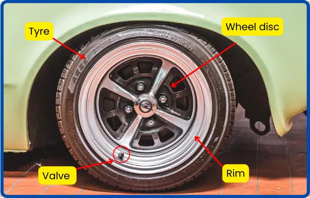
Wheel Rim
The wheel rim is the outer circular part of the wheel that holds the tire. It's usually made of steel or aluminum alloy. Key specs include:
- Diameter: Measured in inches (e.g., 16", 17", 18"), this indicates the size of the tire the rim can accommodate.
- Width: Measured in inches (e.g., 6.5", 7.0", 7.5"), this defines the width of the tire that can be mounted safely and effectively.
- Offset: Measured in millimeters (mm), offset is the distance between the wheel's mounting surface and its centerline. Positive offset means the mounting surface is closer to the outside of the wheel, negative offset means it's closer to the inside. Incorrect offset can cause rubbing, handling issues, and even damage to suspension components.
- Bolt Pattern (PCD): Pitch Circle Diameter (PCD) describes the diameter of the circle formed by the wheel studs or bolt holes. It's crucial to match the PCD of the wheel to that of the vehicle's hub (e.g., 5x114.3mm, meaning 5 studs on a 114.3mm circle).
- Center Bore: The diameter of the hole in the center of the wheel, which centers the wheel on the hub. Some wheels use hub-centric rings to adapt to smaller hub sizes.
Wheel Disc/Center
The wheel disc, also known as the wheel center, is the part of the wheel that connects the rim to the hub. It's the structural component that transmits the forces from the axle to the tire. Key features include:
- Spoke Design: The number and shape of the spokes influence the wheel's strength and aesthetic appeal.
- Material: Typically made of the same material as the rim (steel or alloy), the material impacts weight and durability.
Tire
While technically separate, the tire is integral to the wheel assembly. Tire specifications are printed on the sidewall and include:
- Tire Size: (e.g., 205/55R16) - 205 is the tire width in millimeters, 55 is the aspect ratio (sidewall height as a percentage of width), R indicates radial construction, and 16 is the rim diameter in inches.
- Load Index: A numerical code indicating the maximum load the tire can carry.
- Speed Rating: A letter code indicating the maximum speed at which the tire can be driven safely.
Valve Stem
The valve stem allows air to be added to or released from the tire. It contains a valve core that prevents air leakage.
Wheel Weights
Wheel weights are small weights attached to the rim to balance the wheel and prevent vibration at high speeds. They are typically made of lead or steel and are clipped or adhered to the rim.
Hub Assembly
The hub assembly includes the wheel bearings, which allow the wheel to rotate freely. It also provides the mounting point for the wheel.
Lug Nuts/Bolts
Lug nuts (or lug bolts) secure the wheel to the hub. Correct torque is crucial to prevent wheel loosening or stud damage.
Symbols and Conventions in a Car Wheel Diagram
Diagrams use specific conventions to convey information efficiently. Here are some common examples:
- Cross-sectional lines: Indicate a cut-away view, showing internal components.
- Hidden lines: Dashed lines representing parts hidden from view.
- Centerlines: Thin, long-dashed lines with short dashes in the middle, indicating the center of a circular feature.
- Dimension lines: Lines with arrows at both ends, indicating the length, width, or diameter of a component. The dimension value is usually written above or below the line.
- Tolerance specifications: May be indicated using symbols like ± (plus or minus) followed by a numerical value, specifying the acceptable variation in dimensions.
- Material symbols: Different hatching patterns or colors may represent different materials (e.g., steel, aluminum, rubber).
How It Works: The Wheel System
The wheel system is a crucial part of your vehicle's drivetrain. The engine provides power, which is transmitted through the transmission and axles to the wheels. The wheel, in turn, transmits this rotational force to the tire. The tire's contact with the road surface provides the traction necessary to propel the vehicle forward (or backward). The wheel bearings within the hub assembly allow the wheel to rotate smoothly and with minimal friction. Proper wheel balance (achieved using wheel weights) ensures that the wheel rotates without excessive vibration, improving ride quality and reducing wear on suspension components.
Real-World Use and Basic Troubleshooting
A wheel diagram comes in handy for troubleshooting various issues:
- Vibrations: A diagram can help you check for bent rims, loose lug nuts, or missing wheel weights.
- Tire Wear: Uneven tire wear can indicate alignment issues, incorrect tire pressure, or damaged suspension components. The diagram helps you visualize the relationship between the wheel, tire, and suspension.
- Brake Problems: The wheel diagram often includes the brake rotor and caliper, allowing you to visualize how these components interact with the wheel hub. This is helpful for diagnosing brake noise or performance issues.
- Choosing the Right Wheels/Tires: A diagram helps you understand the necessary dimensions to ensure proper fitment and avoid rubbing.
- Hub Bearing Noise: Locate the hub and related components to perform a check.
Safety Considerations
Working on wheel components involves certain risks:
- Lug Nut Torque: Always use a torque wrench to tighten lug nuts to the manufacturer's specified torque. Overtightening can damage studs or distort the wheel, while undertightening can cause the wheel to loosen and fall off.
- Spring Compression: When working on suspension components (which are often closely related to the wheel assembly), be extremely careful of compressed springs. Releasing a compressed spring without proper tools can cause serious injury.
- Jacking Up the Vehicle: Always use proper jack stands when working under a vehicle. Never rely solely on the jack.
- Tire Inflation: Overinflating a tire can cause it to explode, while underinflating can lead to tire failure. Always inflate tires to the recommended pressure.
Remember to consult your vehicle's repair manual for specific instructions and torque specifications related to your model. Correct information helps ensure safe and effective repairs.
By understanding the parts of a car wheel diagram, you're better equipped to maintain, repair, and modify your vehicle safely and effectively. You can now diagnose many wheel related issues with precision. Download the file below.
[Download Wheel Diagram Here: link to downloadable diagram]