
Plug And Play Car Stereo Wiring Harness
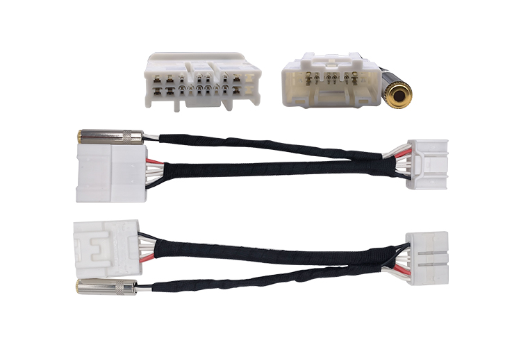
So, you're thinking about upgrading your car stereo, or maybe you're dealing with some faulty wiring? One tool that can save you a ton of time and headaches is a plug and play car stereo wiring harness. This article will break down how these harnesses work, focusing on interpreting their wiring diagrams. Consider this your guide to understanding the complex, but ultimately manageable, world of automotive audio wiring.
Purpose: Why Understanding the Wiring Diagram Matters
Why bother digging into wiring diagrams at all? Several reasons. First, it's invaluable for troubleshooting. If your new stereo isn't powering on, or you're only getting sound from one speaker, a diagram will help you pinpoint the problem. Second, it's crucial for installation. While 'plug and play' implies simplicity, modifications are sometimes needed – especially if you're adding aftermarket amplifiers or other components. A diagram shows you exactly where each wire connects, minimizing the risk of short circuits or damage to your car's electrical system. Third, it’s great for learning. Understanding how your car's audio system is wired gives you a deeper appreciation for the electronics involved and makes future modifications or repairs less daunting.
Key Specs and Main Parts of a Wiring Harness
A plug and play wiring harness isn't just a single bundle of wires. It’s a carefully engineered system designed to interface with your car's factory wiring. Here's a breakdown of the key components:
- Vehicle-Specific Connector: This is the heart of the plug and play system. It's a connector that perfectly matches the factory connector in your car, allowing you to connect the harness without cutting or splicing any wires. This connector is designed to plug directly into your car's existing radio harness.
- Aftermarket Stereo Connector: This connector is designed to plug directly into the back of your new aftermarket stereo. These are often standardized (like an ISO connector), but it's crucial to verify compatibility with your specific radio model.
- Color-Coded Wires: Each wire in the harness is assigned a specific color, following industry standards (though slight variations can occur, so always double-check). These colors correspond to specific functions, such as power, ground, speaker outputs, and remote turn-on for amplifiers.
- Power and Ground Wires: These are typically thicker than the other wires and are responsible for supplying power to the stereo and providing a ground connection. The power wire (usually red or yellow) connects to a fused 12V power source in your car. The ground wire (usually black) connects to a solid grounding point on the car's chassis.
- Speaker Wires: These wires connect to the speakers in your car. There are typically four pairs of speaker wires: one pair for the front left speaker, one for the front right speaker, one for the rear left speaker, and one for the rear right speaker. Each pair consists of a positive (+) and a negative (-) wire.
- Remote Turn-On Wire (Blue): This wire provides a +12V signal when the stereo is turned on. It's used to activate aftermarket amplifiers or other accessories.
- Antenna Adapter (if needed): Some vehicles require an antenna adapter to connect the aftermarket stereo to the car's antenna cable.
Key Specs: When looking at a wiring diagram, pay attention to the wire gauge (thickness). Speaker wires are typically 16-18 gauge, while power and ground wires are often 12-14 gauge (depending on the power requirements of the stereo). Also, note the voltage. Car stereos operate on 12V DC.
Understanding Wiring Diagram Symbols
Wiring diagrams use a standardized set of symbols to represent different components and connections. Here's a breakdown of the most common symbols you'll encounter:
- Lines: Lines represent wires. Solid lines indicate a direct electrical connection, while dashed lines may indicate a shielded wire or a connection that is not always present.
- Colors: As mentioned, colors are crucial. Common colors include:
- Red: 12V Constant Power
- Yellow: 12V Switched Power (Ignition)
- Black: Ground
- White: Front Left Speaker (+)
- White/Black Stripe: Front Left Speaker (-)
- Gray: Front Right Speaker (+)
- Gray/Black Stripe: Front Right Speaker (-)
- Green: Rear Left Speaker (+)
- Green/Black Stripe: Rear Left Speaker (-)
- Purple: Rear Right Speaker (+)
- Purple/Black Stripe: Rear Right Speaker (-)
- Blue: Remote Turn-On
- Icons:
- Circle with a line through it: Ground connection
- Fuse symbol: Represents a fuse, indicating circuit protection
- Battery symbol: Represents the car's battery
- Speaker symbol: Represents a speaker
- Connector symbol: Represents a connector (where wires plug in)
The diagram will typically show the connector pinout – a diagram that illustrates which wire connects to which pin on the connector. This is essential for ensuring you're connecting the right wires to the right places.
How It Works: From Factory Harness to Aftermarket Stereo
The fundamental principle is simple: the plug and play harness bridges the gap between your car's factory wiring and your new stereo. It does this by:
- Receiving Power: The harness connects to the car's 12V power source (through the factory connector) and provides power to the stereo.
- Providing Ground: It establishes a ground connection for the stereo to complete the circuit.
- Routing Speaker Outputs: It routes the audio signals from the stereo to the car's speakers.
- Facilitating Accessory Control: It may provide signals for controlling accessories like amplifiers (through the remote turn-on wire).
The key is that all of this happens without cutting or splicing the original car wiring. This preserves the integrity of your car's electrical system and makes it easy to revert to the original stereo if needed.
Real-World Use: Basic Troubleshooting Tips
Even with a plug and play harness, problems can arise. Here are some common issues and how to troubleshoot them using the wiring diagram:
- No Power: Check the fuse in the power wire. Use a multimeter to verify that you're getting 12V at the power wire connection. Also, ensure the ground wire is securely connected to a good grounding point.
- No Sound from One Speaker: Check the speaker wire connections. Make sure the positive and negative wires are connected correctly to the speaker. Use a multimeter to test the speaker wire for continuity (a complete circuit).
- Stereo Turns On and Off: This could be a loose connection or a faulty ignition wire connection. Use your wiring diagram to identify the correct ignition wire.
- Excessive Noise (Hum or Static): This is often a grounding issue. Ensure the ground wire is securely connected and that there are no other grounding issues in the car's electrical system.
Always double-check the wiring diagram against your car's specific make and model. Wiring colors and pinouts can vary.
Safety Considerations
Working with car electrical systems involves inherent risks. Here are some crucial safety precautions:
- Disconnect the Battery: Before working on any electrical wiring, disconnect the negative terminal of the car battery. This prevents accidental short circuits and electrical shocks.
- Work in a Well-Lit Area: Good visibility is essential for avoiding mistakes.
- Use the Right Tools: Use insulated crimpers, wire strippers, and multimeters designed for automotive use.
- Double-Check Your Work: Before reconnecting the battery, carefully inspect all connections to ensure they are secure and properly insulated.
- Fuses are Critical: Never bypass a fuse. If a fuse blows repeatedly, there's a problem in the circuit that needs to be addressed. Using a higher amperage fuse can cause a fire.
Risky Components: The power wire is the most dangerous component if mishandled. A short circuit in the power wire can quickly overheat and cause a fire. Also, be careful when working near the car's airbag system. Consult your car's repair manual for specific safety precautions related to airbags.
Warning: Working with automotive electrical systems can be dangerous. If you are not comfortable working with electrical wiring, it is best to consult a qualified automotive technician.
By understanding the purpose, components, and symbols of a plug and play car stereo wiring harness diagram, you're well-equipped to tackle your next car audio project with confidence. Remember to always prioritize safety and double-check your work. Happy wiring!
We have a detailed wiring diagram file available for download to aid you in your projects. This diagram is in PDF format, clearly outlining the connections and color codes mentioned in this article. Feel free to download it and use it as a reference guide while working on your car stereo wiring.